Removed text is struck through; added text is highlighted.
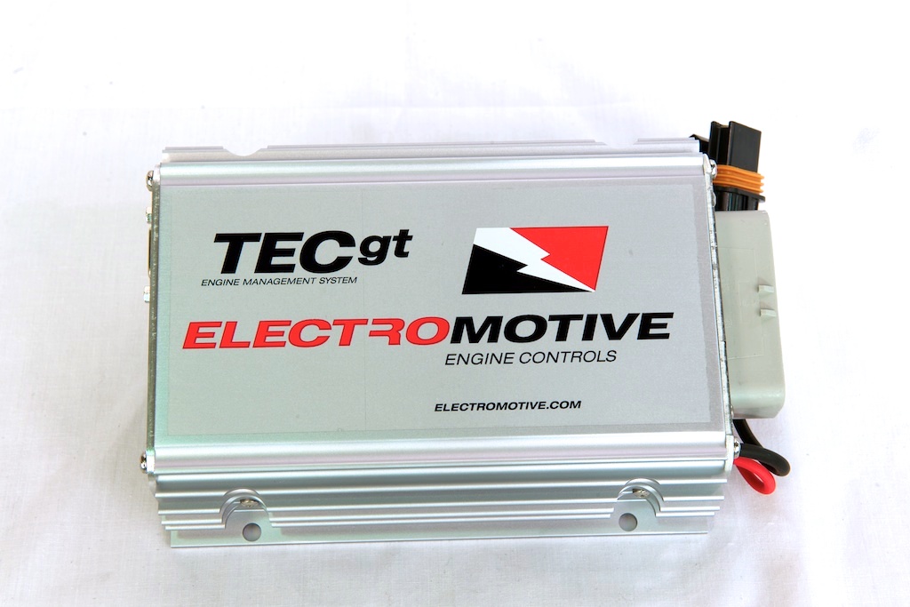
Electromotive TECgt. Image: Electromotive, reproduced with permission.
Electromotive TECgt is a model in the Total Engine Control family. TECgt engine-management ECU with a separate model-specific user guide. It is not identical by designation to TECgt200. Manufacturer source.
Identification and software
Identify the exact model, serial, firmware and ignition-driver configuration before using a calibration or connecting a loom. WinTEC versions and hardware vary; the Electromotive manual archive separates the generations.
Wiring and pinout
Consult the model-specific manufacturer source and technical archive for the matching connector, firing order, ECU earths, injector drivers and ignition connections. Do not transfer TECgt200 or TECs200 positions to earlier TEC units. Where a complete exact-model pinout has not been verified, use the manufacturer documentation and verify the actual part number.
Availability
As of 17 November 2026, the manufacturer states it is not selling or repairing products. Electromotive notice. See the Electromotive family reference.
Manufacturer connector scheduleThe following TECgt grey connector schedule is from Electromotive's model-specific installation manual. Functions marked as alternatives depend on configuration; consult the manual for electrical ratings, connector view and harness details. Colours are those listed for the manufacturer's harness.PinFunctionHarness colourG1Coil channel C1 or A2BlackG2Coil channel B2RedG3Injector channel 5Light blue/blackG4Injector channel 6 or GP I/O 7Light blue/redG5Crank sensor inputRedG6Sensor groundBlack/whiteG7Crank/cam shield and crank sensor groundBareG8+5 V outputGrey/redG9GP I/O 8Orange/blackG10GP I/O 1White/blackG11Injector channel 2Yellow/redG12Injector channel 1Yellow/blackG13DFU shieldBareG14IAC pin A or GP I/O 3Dark blue/blackG15IAC pin B or GP I/O 4Dark blue/whiteG16Data log status lightWhite/orangeG17Fuel pump relay groundLight greenG18Check engine lightPinkG19Tachometer outputBrownG20Speed sensor or GP I/O 2Orange/blueG21MAT inputWhiteG22GP I/O 9Orange/redG23Cam sensor inputRedG24Coil channel B1RedG25Coil channel A1WhiteG26IAC pin C or GP I/O 5Dark green/blackG27IAC pin D or GP I/O 6Dark green/whiteG28CLT inputGreyG29TPS inputDark blueG30MAP inputDark greenG31Knock sensor inputOrangeG32Oxygen sensor −TanG33Oxygen sensor +PurpleG34Injector channel 3Yellow/greenG35Injector channel 4Yellow/blueSeparate two-way power connectorPinFunctionASwitched battery +12 VBBattery ground
Rendered revisions
Open each version to inspect formatting, tables and photographs.
Revision 1: Electromotive TECgt
Electromotive TECgt is a model in the Total Engine Control family. TECgt engine-management ECU with a separate model-specific user guide. It is not identical by designation to TECgt200. Manufacturer source.
Identification and software
Identify the exact model, serial, firmware and ignition-driver configuration before using a calibration or connecting a loom. WinTEC versions and hardware vary; the Electromotive manual archive separates the generations.
Wiring and pinout
Consult the model-specific manufacturer source and technical archive for the matching connector, firing order, ECU earths, injector drivers and ignition connections. Do not transfer TECgt200 or TECs200 positions to earlier TEC units. Where a complete exact-model pinout has not been verified, use the manufacturer documentation and verify the actual part number.
Revision 3: Electromotive TECgtElectromotive TECgt. Image: Electromotive, reproduced with permission.
Electromotive TECgt is a model in the Total Engine Control family. TECgt engine-management ECU with a separate model-specific user guide. It is not identical by designation to TECgt200. Manufacturer source.
Identification and software
Identify the exact model, serial, firmware and ignition-driver configuration before using a calibration or connecting a loom. WinTEC versions and hardware vary; the Electromotive manual archive separates the generations.
Wiring and pinout
Consult the model-specific manufacturer source and technical archive for the matching connector, firing order, ECU earths, injector drivers and ignition connections. Do not transfer TECgt200 or TECs200 positions to earlier TEC units. Where a complete exact-model pinout has not been verified, use the manufacturer documentation and verify the actual part number.
The following TECgt grey connector schedule is from Electromotive's model-specific installation manual. Functions marked as alternatives depend on configuration; consult the manual for electrical ratings, connector view and harness details. Colours are those listed for the manufacturer's harness.