Removed text is struck through; added text is highlighted.
Electromotive TEC3 is a model in the Total Engine Control family. TEC3 engine-management system documented in the manufacturer’s installation and calibration manual, version 1.7. Manufacturer source.
Identification and software
Identify the exact model, serial, firmware and ignition-driver configuration before using a calibration or connecting a loom. WinTEC versions and hardware vary; the Electromotive manual archive separates the generations.
Wiring and pinout
Consult the model-specific manufacturer source and technical archive for the matching connector, firing order, ECU earths, injector drivers and ignition connections. Do not transfer TECgt200 or TECs200 positions to earlier TEC units. Where a complete exact-model pinout has not been verified, use the manufacturer documentation and verify the actual part number.
Availability
As of 17 November 2026, the manufacturer states it is not selling or repairing products. Electromotive notice. See the Electromotive family reference.
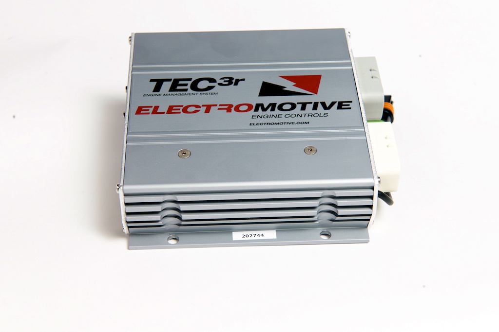
Manufacturer connector schedulesElectromotive's TEC3 manual version 1.7, pages 165–170, gives different output connectors for the standard TEC3 and the TEC3 6/12. The grey connector is shared between those configurations. W16/W17 are unused on TEC3 6/12, unlike TEC3r. Match the ECU and loom before wiring. Wire colours are the manufacturer harness colours; a slash denotes the stripe. G21 may be white/black on early harnesses. Outputs G1/G2/G20/G21 together and outputs B18–B21 or W18–W21 together each have a combined maximum of 4 A in the manual.Standard TEC3 black 23-way connectorPinFunctionHarness wireB1Coil channel AWhiteB2Coil channel BRedB3Coil channel CBlackB4Coil channel DRedB5Injector channel 1Yellow/blackB6Injector channel 2Yellow/redB7Injector channel 3Yellow/greenB8Injector channel 4Yellow/blueB9Injector channel 5Light blue/blackB10Coil wire shieldBareB11Idle air control DDark blue/whiteB12Idle air control CDark blue/blackB13Idle air control BDark green/whiteB14Idle air control ADark green/blackB15Injector channel 6Light blue/redB16Unused—B17Unused—B18General-purpose output 1White/blackB19General-purpose output 2White/redB20General-purpose output 3White/greenB21General-purpose output 4White/blueB22Injector channel 7Light blue/greenB23Injector channel 8Light blue/blueTEC3 6/12 white 23-way connectorPinFunctionHarness wireW1Coil channel A1WhiteW2Coil channel B1RedW3Coil channel C1BlackW4Coil channel A2WhiteW5Coil channel B2RedW6Coil channel C2BlackW7Injector channel 1Yellow/blackW8Injector channel 2Yellow/redW9Injector channel 3Yellow/greenW10Coil wire shieldBareW11Idle air control DDark blue/whiteW12Idle air control CDark blue/blackW13Idle air control BDark green/whiteW14Idle air control ADark green/blackW15Injector channel 4Yellow/blueW16Unused—W17Unused—W18General-purpose output 1White/blackW19General-purpose output 2White/redW20General-purpose output 3White/greenW21General-purpose output 4White/blueW22Injector channel 5Light blue/blackW23Injector channel 6Light blue/redGrey 23-way connector, standard and 6/12PinFunctionHarness wireG1Tachometer outputBrownG2Check-engine lightPinkG3+5 V outputGrey/redG4Crank/cam groundBlackG5Switched +12 V inputYellowG6Oxygen sensor negativeTanG7Oxygen sensor positiveVioletG8Knock sensor inputOrangeG9Crank sensor inputRed, shieldedG10Cam sensor inputRed, shieldedG11Crank/cam shieldBareG12Coolant temperature inputGreyG13Manifold air temperature inputWhiteG14Throttle position inputDark blueG15MAP inputDark greenG16General-purpose input 1Orange/blackG17General-purpose input 2Orange/redG18General-purpose input 3Orange/greenG19General-purpose input 4Orange/blueG20Fuel pump relay groundLight greenG21Datalog status light groundWhite/orangeG22Sensor groundBlack/whiteG23Unused—Two-way ECU power connectorPositionFunctionHarness wireA+12 V inputRedBMain battery groundBlackStandard TEC3 direct-fire-unit harness plugsPositionDFU ADFU BACoil ACoil CBCoil BCoil DCCoil CUnusedD+12 V coil power+12 V coil powerTEC3 6/12 direct-fire-unit harness plugsPositionDFU ADFU BACoil A1Coil A2BCoil B1Coil B2CCoil C1Coil C2D+12 V coil power+12 V coil powerDFU position D is supplied by the separately fused coil-power wiring; the original harness diagrams specify 9 A for each DFU.Serial communication connectorThe AiM integration guide identifies these DB9 signal positions; other cavities are not specified in that guide.DB9 communicationsPinFunction2ECU RS-232 transmit3ECU RS-232 receive5Signal groundTEC3r shown as a related TEC3-family illustration; the TEC3 and TEC3r wiring and configuration may differ. Image: Electromotive, reproduced with permission.
Rendered revisions
Open each version to inspect formatting, tables and photographs.
Revision 1: Electromotive TEC3
Electromotive TEC3 is a model in the Total Engine Control family. TEC3 engine-management system documented in the manufacturer’s installation and calibration manual, version 1.7. Manufacturer source.
Identification and software
Identify the exact model, serial, firmware and ignition-driver configuration before using a calibration or connecting a loom. WinTEC versions and hardware vary; the Electromotive manual archive separates the generations.
Wiring and pinout
Consult the model-specific manufacturer source and technical archive for the matching connector, firing order, ECU earths, injector drivers and ignition connections. Do not transfer TECgt200 or TECs200 positions to earlier TEC units. Where a complete exact-model pinout has not been verified, use the manufacturer documentation and verify the actual part number.
Electromotive TEC3 is a model in the Total Engine Control family. TEC3 engine-management system documented in the manufacturer’s installation and calibration manual, version 1.7. Manufacturer source.
Identification and software
Identify the exact model, serial, firmware and ignition-driver configuration before using a calibration or connecting a loom. WinTEC versions and hardware vary; the Electromotive manual archive separates the generations.
Wiring and pinout
Consult the model-specific manufacturer source and technical archive for the matching connector, firing order, ECU earths, injector drivers and ignition connections. Do not transfer TECgt200 or TECs200 positions to earlier TEC units. Where a complete exact-model pinout has not been verified, use the manufacturer documentation and verify the actual part number.
Electromotive's TEC3 manual version 1.7, pages 165–170, gives different output connectors for the standard TEC3 and the TEC3 6/12. The grey connector is shared between those configurations. W16/W17 are unused on TEC3 6/12, unlike TEC3r. Match the ECU and loom before wiring. Wire colours are the manufacturer harness colours; a slash denotes the stripe. G21 may be white/black on early harnesses. Outputs G1/G2/G20/G21 together and outputs B18–B21 or W18–W21 together each have a combined maximum of 4 A in the manual.
Standard TEC3 black 23-way connector
Pin
Function
Harness wire
B1
Coil channel A
White
B2
Coil channel B
Red
B3
Coil channel C
Black
B4
Coil channel D
Red
B5
Injector channel 1
Yellow/black
B6
Injector channel 2
Yellow/red
B7
Injector channel 3
Yellow/green
B8
Injector channel 4
Yellow/blue
B9
Injector channel 5
Light blue/black
B10
Coil wire shield
Bare
B11
Idle air control D
Dark blue/white
B12
Idle air control C
Dark blue/black
B13
Idle air control B
Dark green/white
B14
Idle air control A
Dark green/black
B15
Injector channel 6
Light blue/red
B16
Unused
—
B17
Unused
—
B18
General-purpose output 1
White/black
B19
General-purpose output 2
White/red
B20
General-purpose output 3
White/green
B21
General-purpose output 4
White/blue
B22
Injector channel 7
Light blue/green
B23
Injector channel 8
Light blue/blue
TEC3 6/12 white 23-way connector
Pin
Function
Harness wire
W1
Coil channel A1
White
W2
Coil channel B1
Red
W3
Coil channel C1
Black
W4
Coil channel A2
White
W5
Coil channel B2
Red
W6
Coil channel C2
Black
W7
Injector channel 1
Yellow/black
W8
Injector channel 2
Yellow/red
W9
Injector channel 3
Yellow/green
W10
Coil wire shield
Bare
W11
Idle air control D
Dark blue/white
W12
Idle air control C
Dark blue/black
W13
Idle air control B
Dark green/white
W14
Idle air control A
Dark green/black
W15
Injector channel 4
Yellow/blue
W16
Unused
—
W17
Unused
—
W18
General-purpose output 1
White/black
W19
General-purpose output 2
White/red
W20
General-purpose output 3
White/green
W21
General-purpose output 4
White/blue
W22
Injector channel 5
Light blue/black
W23
Injector channel 6
Light blue/red
Grey 23-way connector, standard and 6/12
Pin
Function
Harness wire
G1
Tachometer output
Brown
G2
Check-engine light
Pink
G3
+5 V output
Grey/red
G4
Crank/cam ground
Black
G5
Switched +12 V input
Yellow
G6
Oxygen sensor negative
Tan
G7
Oxygen sensor positive
Violet
G8
Knock sensor input
Orange
G9
Crank sensor input
Red, shielded
G10
Cam sensor input
Red, shielded
G11
Crank/cam shield
Bare
G12
Coolant temperature input
Grey
G13
Manifold air temperature input
White
G14
Throttle position input
Dark blue
G15
MAP input
Dark green
G16
General-purpose input 1
Orange/black
G17
General-purpose input 2
Orange/red
G18
General-purpose input 3
Orange/green
G19
General-purpose input 4
Orange/blue
G20
Fuel pump relay ground
Light green
G21
Datalog status light ground
White/orange
G22
Sensor ground
Black/white
G23
Unused
—
Two-way ECU power connector
Position
Function
Harness wire
A
+12 V input
Red
B
Main battery ground
Black
Standard TEC3 direct-fire-unit harness plugs
Position
DFU A
DFU B
A
Coil A
Coil C
B
Coil B
Coil D
C
Coil C
Unused
D
+12 V coil power
+12 V coil power
TEC3 6/12 direct-fire-unit harness plugs
Position
DFU A
DFU B
A
Coil A1
Coil A2
B
Coil B1
Coil B2
C
Coil C1
Coil C2
D
+12 V coil power
+12 V coil power
DFU position D is supplied by the separately fused coil-power wiring; the original harness diagrams specify 9 A for each DFU.
Serial communication connector
The AiM integration guide identifies these DB9 signal positions; other cavities are not specified in that guide.
DB9 communications
Pin
Function
2
ECU RS-232 transmit
3
ECU RS-232 receive
5
Signal ground
TEC3r shown as a related TEC3-family illustration; the TEC3 and TEC3r wiring and configuration may differ. Image: Electromotive, reproduced with permission.