Removed text is struck through; added text is highlighted.
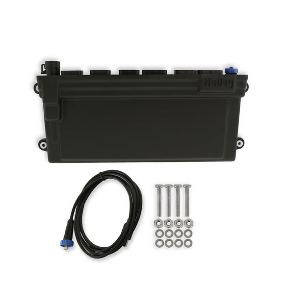
Holley EFI Dominator. Image: Holley; reproduced with user-confirmed permission.
Holley EFI Dominator is a programmable US Holley engine-control unit; ECU part number 554-114 is listed by Holley. Holley ECU and harness parts guide · manufacturer comparison.
Identification and capabilities
The Dominator has six ECU connectors, two wideband channels, USB PC communication, internal/external logging and substantially expanded inputs and outputs. It can control supported drive-by-wire and automatic-transmission installations with the correct hardware, harness and software.
HardwareManufacturer descriptionECU identifier554-114Injector drivers12 injector drivers with high- and low-impedance supportModel-specific distinctionJ1A/J1B are only the common main connectors. Additional Dominator connectors require the exact Dominator wiring and function allocation; never infer their pins from HP or Terminator.
Injector impedance, timing hardware, firmware, sensor types and output allocation determine compatibility. Kits may use a model ECU with different vehicle-specific main and injector harnesses.
J1A and J1B ECU pinouts
Holley's ECU pinout gives J1A and J1B for HP, Dominator, Terminator X and X Max; this table records the Dominator interpretation. Source naming and ratings are preserved; verify connector orientation and model-specific harness, fuse and configuration before connection.
Connector J1A
PositionFunctionA1Coil negative inputA2Fuel pump output +12 V (10 A maximum)A3Input 2 (capabilities depend on model)A4Input 4 (capabilities depend on model)A5TPS inputA6Points trigger outputA7Wideband 1 COMPR2A8Wideband 1 shieldA9Wideband heater negativeA10Switched +12 V inputA11Manifold air temperature inputA12Input 1 (capabilities depend on model)A13Input 3 (capabilities depend on model)A14Cam/crank groundA15Gauge digital outputA16Wideband 1 COMPR1A17Wideband 1 VS−/IP+A18Sensor groundA19Engine coolant temperature inputA20Oil pressure inputA21Knock 2 inputA22Cam sync input / ignition bypass outputA23MAP sensor inputA24CAN lowA25Wideband 1 VS+A26Sensor +5 VA27Not usedA28EST/Spout outputA29Knock 1 inputA30Crank speed inputA31Fuel pressure inputA32CAN highA33Wideband 1 IP+A34Wideband heater positive
Connector J1B
PositionFunctionB1IAC A lowB2IAC A highB3Output 4 (ground/PWM−)B4Injector FB5Injector GB6Injector HB7Injector EB8IAC B lowB9IAC B highB10Output 3 (ground/PWM−)B11Output 2 (high-side / PWM+)B12Output 1 (high-side / PWM+)B13Injector DB14EST ground outputB15EST 2 (cylinder 2)B16EST 4 (cylinder 4)B17EST 6 (cylinder 6)B18EST 8 (cylinder 8)B19Injector AB20EST 12 V outputB21EST 1 (cylinder 1)B22EST 3 (cylinder 3)B23EST 5 (cylinder 5)B24EST 7 (cylinder 7)B25Injector CB26Injector B
Input type codes and B11/B12 drive polarity vary across the families; refer to Holley's auxiliary I/O harness guide. Additional connectors are not represented by this table.
Software and sources
Holley EFI software and supportMain connector pinout and manufacturer cautionsECU, engine and ignition harness selectionHolley EFI family index
Source review: 17 November 2026.
Rendered revisions
Open each version to inspect formatting, tables and photographs.
Revision 2: Holley EFI DominatorHolley EFI Dominator. Image: Holley; reproduced with user-confirmed permission.
The Dominator has six ECU connectors, two wideband channels, USB PC communication, internal/external logging and substantially expanded inputs and outputs. It can control supported drive-by-wire and automatic-transmission installations with the correct hardware, harness and software.
Hardware
Manufacturer description
ECU identifier
554-114
Injector drivers
12 injector drivers with high- and low-impedance support
Model-specific distinction
J1A/J1B are only the common main connectors. Additional Dominator connectors require the exact Dominator wiring and function allocation; never infer their pins from HP or Terminator.
Injector impedance, timing hardware, firmware, sensor types and output allocation determine compatibility. Kits may use a model ECU with different vehicle-specific main and injector harnesses.
J1A and J1B ECU pinouts
Holley's ECU pinout gives J1A and J1B for HP, Dominator, Terminator X and X Max; this table records the Dominator interpretation. Source naming and ratings are preserved; verify connector orientation and model-specific harness, fuse and configuration before connection.
Connector J1A
Position
Function
A1
Coil negative input
A2
Fuel pump output +12 V (10 A maximum)
A3
Input 2 (capabilities depend on model)
A4
Input 4 (capabilities depend on model)
A5
TPS input
A6
Points trigger output
A7
Wideband 1 COMPR2
A8
Wideband 1 shield
A9
Wideband heater negative
A10
Switched +12 V input
A11
Manifold air temperature input
A12
Input 1 (capabilities depend on model)
A13
Input 3 (capabilities depend on model)
A14
Cam/crank ground
A15
Gauge digital output
A16
Wideband 1 COMPR1
A17
Wideband 1 VS−/IP+
A18
Sensor ground
A19
Engine coolant temperature input
A20
Oil pressure input
A21
Knock 2 input
A22
Cam sync input / ignition bypass output
A23
MAP sensor input
A24
CAN low
A25
Wideband 1 VS+
A26
Sensor +5 V
A27
Not used
A28
EST/Spout output
A29
Knock 1 input
A30
Crank speed input
A31
Fuel pressure input
A32
CAN high
A33
Wideband 1 IP+
A34
Wideband heater positive
Connector J1B
Position
Function
B1
IAC A low
B2
IAC A high
B3
Output 4 (ground/PWM−)
B4
Injector F
B5
Injector G
B6
Injector H
B7
Injector E
B8
IAC B low
B9
IAC B high
B10
Output 3 (ground/PWM−)
B11
Output 2 (high-side / PWM+)
B12
Output 1 (high-side / PWM+)
B13
Injector D
B14
EST ground output
B15
EST 2 (cylinder 2)
B16
EST 4 (cylinder 4)
B17
EST 6 (cylinder 6)
B18
EST 8 (cylinder 8)
B19
Injector A
B20
EST 12 V output
B21
EST 1 (cylinder 1)
B22
EST 3 (cylinder 3)
B23
EST 5 (cylinder 5)
B24
EST 7 (cylinder 7)
B25
Injector C
B26
Injector B
Input type codes and B11/B12 drive polarity vary across the families; refer to Holley's auxiliary I/O harness guide. Additional connectors are not represented by this table.
The Dominator has six ECU connectors, two wideband channels, USB PC communication, internal/external logging and substantially expanded inputs and outputs. It can control supported drive-by-wire and automatic-transmission installations with the correct hardware, harness and software.
Hardware
Manufacturer description
ECU identifier
554-114
Injector drivers
12 injector drivers with high- and low-impedance support
Model-specific distinction
J1A/J1B are only the common main connectors. Additional Dominator connectors require the exact Dominator wiring and function allocation; never infer their pins from HP or Terminator.
Injector impedance, timing hardware, firmware, sensor types and output allocation determine compatibility. Kits may use a model ECU with different vehicle-specific main and injector harnesses.
J1A and J1B ECU pinouts
Holley's ECU pinout gives J1A and J1B for HP, Dominator, Terminator X and X Max; this table records the Dominator interpretation. Source naming and ratings are preserved; verify connector orientation and model-specific harness, fuse and configuration before connection.
Connector J1A
Position
Function
A1
Coil negative input
A2
Fuel pump output +12 V (10 A maximum)
A3
Input 2 (capabilities depend on model)
A4
Input 4 (capabilities depend on model)
A5
TPS input
A6
Points trigger output
A7
Wideband 1 COMPR2
A8
Wideband 1 shield
A9
Wideband heater negative
A10
Switched +12 V input
A11
Manifold air temperature input
A12
Input 1 (capabilities depend on model)
A13
Input 3 (capabilities depend on model)
A14
Cam/crank ground
A15
Gauge digital output
A16
Wideband 1 COMPR1
A17
Wideband 1 VS−/IP+
A18
Sensor ground
A19
Engine coolant temperature input
A20
Oil pressure input
A21
Knock 2 input
A22
Cam sync input / ignition bypass output
A23
MAP sensor input
A24
CAN low
A25
Wideband 1 VS+
A26
Sensor +5 V
A27
Not used
A28
EST/Spout output
A29
Knock 1 input
A30
Crank speed input
A31
Fuel pressure input
A32
CAN high
A33
Wideband 1 IP+
A34
Wideband heater positive
Connector J1B
Position
Function
B1
IAC A low
B2
IAC A high
B3
Output 4 (ground/PWM−)
B4
Injector F
B5
Injector G
B6
Injector H
B7
Injector E
B8
IAC B low
B9
IAC B high
B10
Output 3 (ground/PWM−)
B11
Output 2 (high-side / PWM+)
B12
Output 1 (high-side / PWM+)
B13
Injector D
B14
EST ground output
B15
EST 2 (cylinder 2)
B16
EST 4 (cylinder 4)
B17
EST 6 (cylinder 6)
B18
EST 8 (cylinder 8)
B19
Injector A
B20
EST 12 V output
B21
EST 1 (cylinder 1)
B22
EST 3 (cylinder 3)
B23
EST 5 (cylinder 5)
B24
EST 7 (cylinder 7)
B25
Injector C
B26
Injector B
Input type codes and B11/B12 drive polarity vary across the families; refer to Holley's auxiliary I/O harness guide. Additional connectors are not represented by this table.