Removed text is struck through; added text is highlighted.
Link G5 Voodoo Pro V2 is a later documented Voodoo Pro version. The V2 quick-start guide describes ECU headers A, B and E, plus separate Ethernet and four-way CAN 1 connectors.
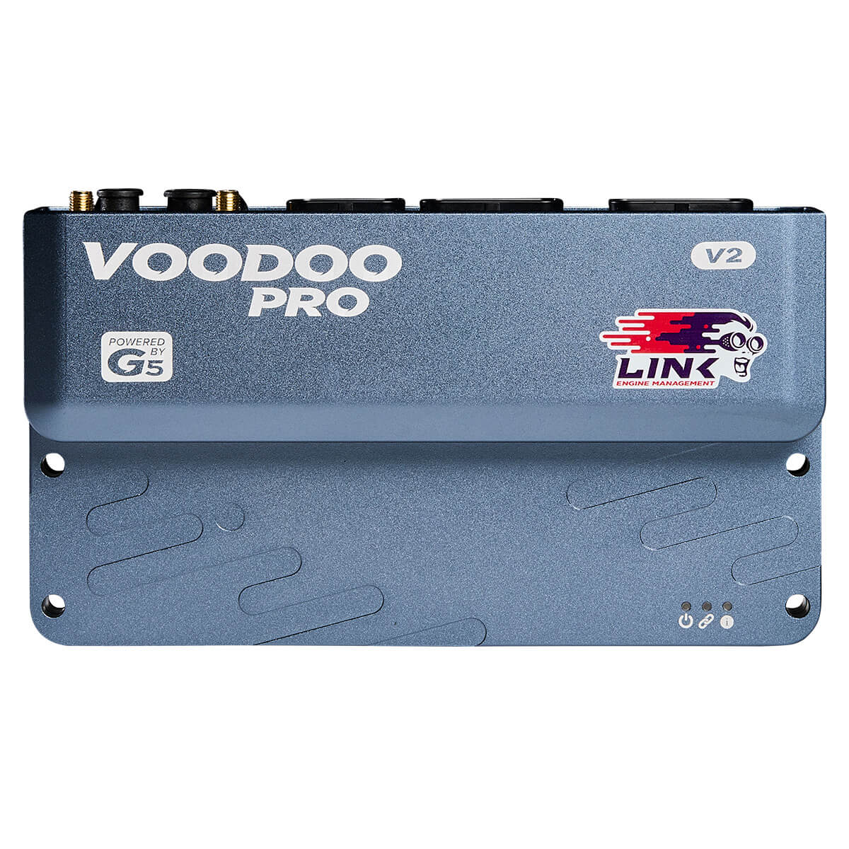
Voodoo Pro V2 product photograph: Link ECU. Permission to republish confirmed by the user.
V2-specific power and communications
The V2 guide identifies A5 as the main ECU supply, A6 as the ignition-switch input and B5 as the H-bridge supply. CAN 1 is a four-way connector: pin 1 ground, 2 CAN low, 3 CAN high and 4 power. The guide specifies connector pin 1 relative to the locator notch, not mounted orientation. Link V2 guide.
Its eight ADIO pins support shared analogue, digital-input and auxiliary-output roles with different limits by function; the same pin cannot be allocated to separate simultaneous functions. The V2 has a different communications layout from V1: select the correct guide.
Connector pinoutHeaders A, B and E (94 cavities) are drawn, with every cavity indexed, in the Link G5 Voodoo Pro V2 connector pinout.
See Voodoo Pro overview for shared platform context. Identify revision and wiring before connecting power.
SourcesLink Engine Management: G5 Voodoo Pro V2 quick-start guide, document version 1.0, manufacturer documentation. Accessed 19 November 2026.
Rendered revisions
Open each version to inspect formatting, tables and photographs.
Revision 1: Link G5 Voodoo Pro V2
Link G5 Voodoo Pro V2 is a later documented Voodoo Pro version. The V2 quick-start guide describes ECU headers A, B and E, plus separate Ethernet and four-way CAN 1 connectors.
Voodoo Pro V2 product photograph: Link ECU. Permission to republish confirmed by the user.
V2-specific power and communications
The V2 guide identifies A5 as the main ECU supply, A6 as the ignition-switch input and B5 as the H-bridge supply. CAN 1 is a four-way connector: pin 1 ground, 2 CAN low, 3 CAN high and 4 power. The guide specifies connector pin 1 relative to the locator notch, not mounted orientation. Link V2 guide.
Its eight ADIO pins support shared analogue, digital-input and auxiliary-output roles with different limits by function; the same pin cannot be allocated to separate simultaneous functions. The V2 has a different communications layout from V1: select the correct guide.
See Voodoo Pro overview for shared platform context. Identify revision and wiring before connecting power.
Revision 2: Link G5 Voodoo Pro V2
Link G5 Voodoo Pro V2 is a later documented Voodoo Pro version. The V2 quick-start guide describes ECU headers A, B and E, plus separate Ethernet and four-way CAN 1 connectors.
Voodoo Pro V2 product photograph: Link ECU. Permission to republish confirmed by the user.
V2-specific power and communications
The V2 guide identifies A5 as the main ECU supply, A6 as the ignition-switch input and B5 as the H-bridge supply. CAN 1 is a four-way connector: pin 1 ground, 2 CAN low, 3 CAN high and 4 power. The guide specifies connector pin 1 relative to the locator notch, not mounted orientation. Link V2 guide.
Its eight ADIO pins support shared analogue, digital-input and auxiliary-output roles with different limits by function; the same pin cannot be allocated to separate simultaneous functions. The V2 has a different communications layout from V1: select the correct guide.