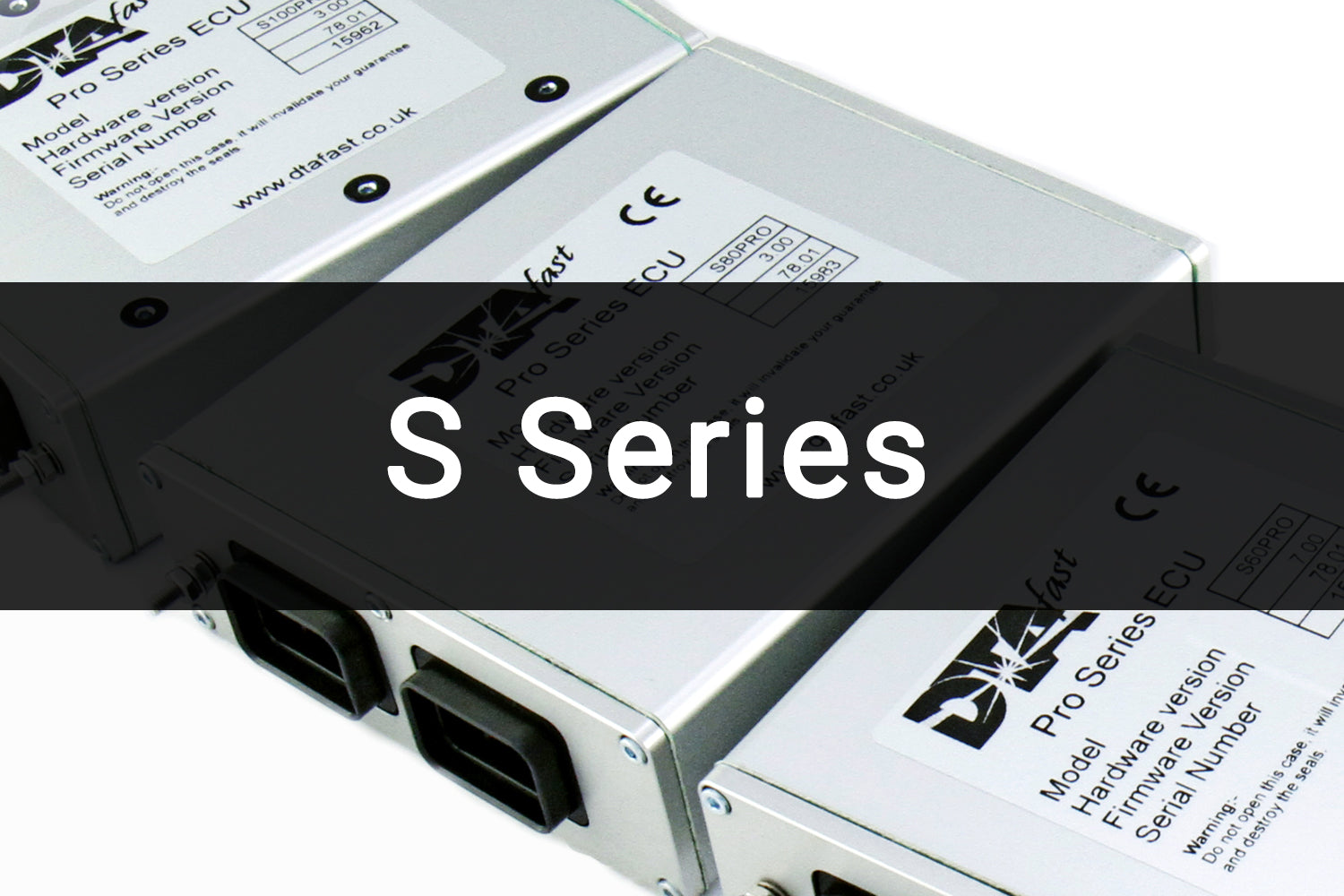
The DTAFast S80 Pro is an S-series programmable engine-management unit. Eight injector and eight coil drivers with two cam inputs in the historical DTA feature matrix. The S-series manual describes traction control on S80 Pro and above. DTAFast historical S-series feature matrix.
Hardware and operation
Refer to the manufacturer S80 Pro connector diagrams, sensor options and notes; outputs can be shared by configurable functions. Confirm the complete ECU label and revision; similarly named S-series units are separate records, and S-series capability differs from T-series. Record the number of injectors, coil arrangement, cam triggers and assigned auxiliary outputs before selecting a calibration.
Wiring and pinout
DTAFast S80 connector pinout and wiring gives connector views, supplies, grounds, sensor and actuator examples. Consult the documented firmware and circuit protection conditions; identify connector keyways and view direction before counting pins. A shared input or output can perform only the function assigned to it.
Software and additional references
The DTAFast S-series Pro manual describes DTASwin calibration software, data logging and model-specific settings. DTAFast S60 Pro product sheet provides an example of output and engine configuration limits. See the DTAFast model family for other ECUs.
S80 Pro pinout — manufacturer diagram
Power and sensor plugs are distinct 34-way connectors. The power connector is shown with three keyways, the sensor connector with four; each set of pin numbers begins at 1. DTAFast's S80 Pro wiring diagram is dated 18 November 2014 and specifies firmware V77.00 or later for all illustrated options. Both connector views are drawn from the pin-insertion side. These tables transcribe the functions shown; unlisted pins are not established as unused. Slash-separated labels are alternatives or configuration-dependent functions.
Power connections
| Pin | Documented function |
|---|---|
| 1 | Coil 3 |
| 2 | Aux 9 / tacho |
| 3 | Aux 7 / fuel pump relay |
| 4 | Aux 2 / fan relay |
| 5 | Aux 1 / cam control |
| 6 | Aux 8 / shift light / electric dump valve |
| 7 | Turbo pressure valve |
| 8 | Idle valve |
| 9 | Injector 1 |
| 10 | Coil 1 |
| 11 | Coil 5 |
| 12 | Coil 7 |
| 13, 14 | Power grounds |
| 15 | Injector 6 |
| 16 | Injector 5 |
| 17 | Injector 2 |
| 18 | Coil 2 |
| 19 | Coil 8 |
| 21 | Cam 2 |
| 23 | Injector 8 |
| 24 | Injector 7 |
| 25 | Injector 4 |
| 26 | Coil 4 |
| 27 | Coil 6 |
| 29 | Aux 5 (12 V output) |
| 30 | Aux 6 |
| 31 | Fused 12 V supply |
| 32 | Aux 4 / ALS / VTEC |
| 33 | Aux 3 / VTEC / Bosch 3-pin idle valve fast side |
| 34 | Injector 3 |
Sensor connections
| Pin | Documented function |
|---|---|
| 1 | Analogue 2 / log switch / TPS 2 |
| 2 | Undriven wheel speed, Hall effect |
| 3 | Analogue 3 / gear potentiometer |
| 4 | Launch button |
| 5 | Oil pressure |
| 6 | Fuel pressure |
| 7 | Air temperature |
| 9 | 5 V output |
| 10 | Analogue 1 / traction cut percentage / launch RPM |
| 12 | Crank magnetic |
| 13 | Crank Hall effect |
| 14 | Shift cut / E85 / air-con / shaft speed |
| 15 | ALS / map 2 / lambda switch |
| 16 | Manifold / barometric pressure |
| 17 | Oil temperature |
| 19 | Left or only lambda signal |
| 21, 33 | Sensor ground |
| 22 | Cam magnetic |
| 23 | Cam Hall effect |
| 25 | Water temperature |
| 26 | CAN high |
| 28 | CAN low |
| 34 | Throttle position |
| 8 | Traction on/off switch |
| 11 | Traction wet/dry switch |
| 18 | Right lambda or launch RPM |
| 20 | Right undriven wheel speed |
| 24 | 5 V output |
| 27 | Aux switch / pit lane speed |
| 29 | Cam 2 Hall effect |
| 30 | Cam 2 magnetic |
| 31 | Left driven wheel speed |
| 32 | Right driven wheel speed |
The manufacturer diagram identifies the power connector's coil and injector outputs by firing order, not necessarily cylinder number. Separate crank and cam Hall and magnetic inputs are alternatives: the diagram says to use only one type per sensor. Check the exact model, keying, orientation, calibration and electrical ratings in the original diagram before wiring.