Removed text is struck through; added text is highlighted.
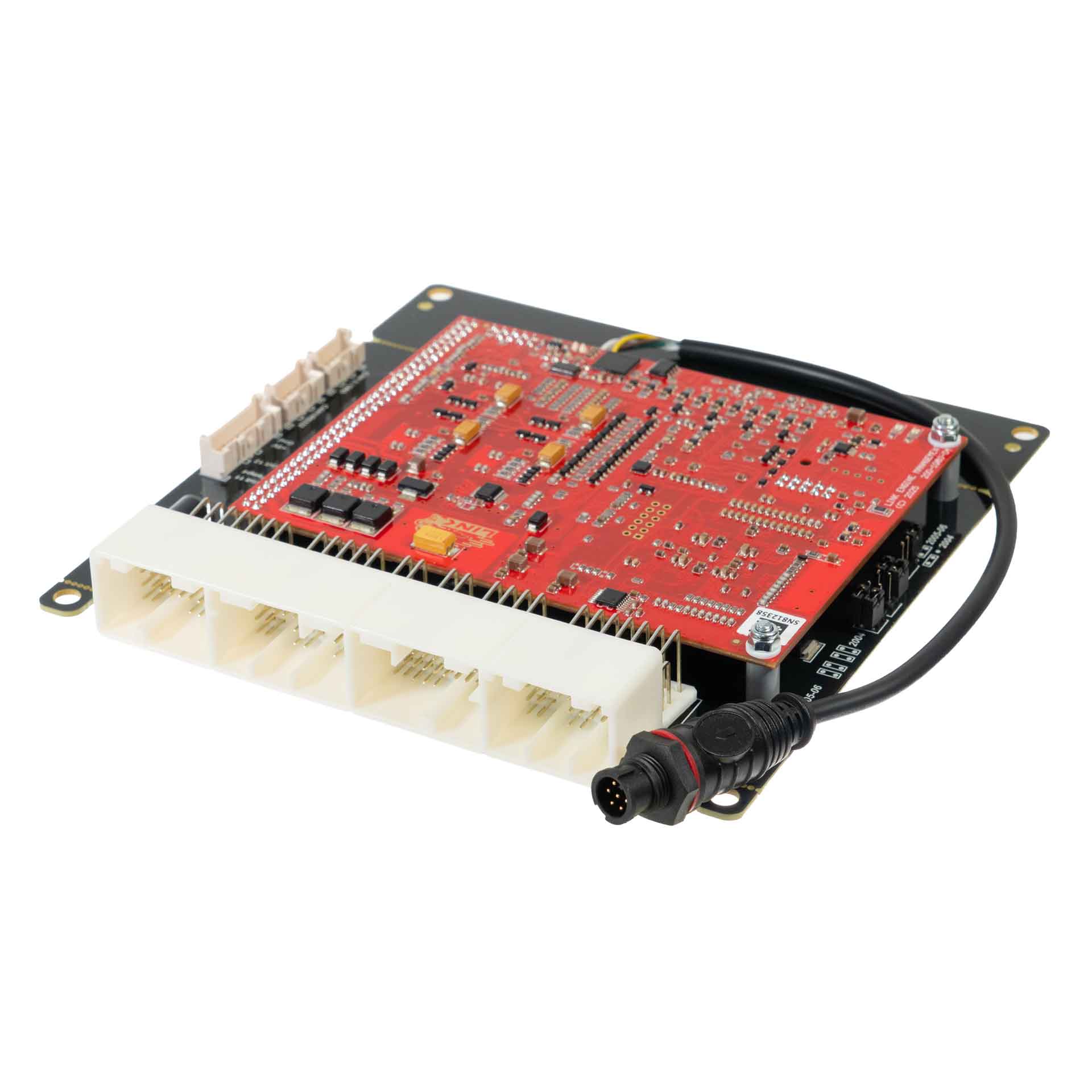
Manufacturer product image of WRX104X application ECU: Link ECU. Permission to republish confirmed by the user.
Link G4X WRX104X is a vehicle-specific programmable plug-in ECU for the Subaru WRX 2004 application application listed in Link's model-specific manuals index. It is an application board, rather than the universal wire-in ECU. Check the exact vehicle, market, engine, original ECU and board part number against the manufacturer's WRX104X installation manual.
Identification and installation
Record the Link model label and revision, donor factory ECU connector and car's engine and year. Plug-in boards connect to particular factory-harness layouts; the family or vehicle name alone does not establish every model-year or transmission combination. The manufacturer manual gives the supported application and any installation or configuration notes for this board.
G4X plug-in platforms offer configurable fuel and ignition control but available channels and features depend on the original header and board. The G4X plug-in general specifications are conditional on the particular application and do not mean every input is brought out to the factory harness.
Pinout and tuning
The WRX104X installation manual is the model-specific source for board pinouts, expansion connections, electrical cautions and startup configuration. Use its connector orientation and the exact board version; do not copy a wire-in ECU pinout onto a factory harness. PCLink and manual downloads; Link manufacturer overview.
Manufacturer connector schedulesFrom Link's WRX10X installation manual. Link describes the pinout view as looking into the ECU from the wire side. A dash reproduces an unspecified source field; nc is Link's label. Confirm the vehicle, market and board revision before use.This is the 2004–2006 schedule from the shared WRXLink (04)/(07) guide. Do not substitute it for the other generation’s header.Factory main headerFactory pinLink ECU channelFactory functionA1DI 4Clutch SwitchC3Injector 4InjectionA2nc—C4Injector 3InjectionA3nc—C5Injector 2InjectionA4nc—C6Injector 1InjectionA5nc—C7DI10Cruise MainA6Ground—C8nc (Brake NO)—A7nc—C9DI 5Brake Switch (NC)A8Aux 8Tumble Valves CloseC10DI 6Cruise Cancel OR ResumeA9Linked to A10TGV wired in seriesC11DI 7Cruise Set OR CancelA10Linked to A9—C12An Temp 3Fuel TemperatureA11Aux 7Tumble Valves OpenC13An Temp 2IAT from MAFA12nc—C14An Temp 1ECTA13nc—C15+5V Out—A14Injector 5 (Aux)Purge SolenoidC16+5V Out—A15Injector 6 (Aux)Cruise LightC17An Volt 10APS (Main)A16nc (Cruise Set Light)—C18An Volt 2TPS (Main)A17Injector 8 (Aux)CE LightC19nc—A18+14V OutAVCS SolenoidC20nc—A19+14V OutAVCS SolenoidC21nc—A20nc—C22An Volt 1MAPA21nc—C23An Volt 8MAF SignalA22nc—C24nc—A23Aux 3TachoC25Knock 1KnockA24nc—C26An Volt 4Left TGV PositionA25Ground—C27An Volt 5Right TGV PositionA26nc—C28An Volt 9APS (Sub)A27nc—C29An Volt 3TPS (Sub)A28Aux 2Bank 1 (RH) AVCS SolenoidC30nc—A29Aux 1Bank 2 (LH) AVCS SolenoidC31Ground (AFM)—A30nc—C32Ground (AFM Shield)—A31nc—C33Ground (Knock Shield)—A32Aux 5Wastegate SolenoidC34Ground (APS)—A33nc—C35Ground (Signal)—A34Ground (Signal)—D1Ground (Signal)—B1Ground—D2Ground (Signal)—B2Injector 7 (Aux)Rear Oxy HeaterD3Ground—B3nc—D4Aux 9EThrottle Motor +B4Ground—D5Aux 10EThrottle Motor -B5+14V Main RelayECU PowerD6+14V EThrottleFrom EThrottle RelayB6+14V Main RelayECU PowerD7Ground—B7nc—D8DI 8Start SignalB8Trig 2Bank 2 (LH) Cam PositionD9DI 9Neutral SignalB9DI 2Bank 1 (RH) Cam PositionD10An Volt 6Power Steer SwitchB10Trig 1Trig 1 (Crank)D11nc—B11nc—D12nc—B12Ground—D13nc—B13nc—D14Ignition Switch (05- 06)Controls Main Relay (05-06)B14nc—D15Ignition Switch (04)Controls Main Relay (04)B15Ignition 4IgnitionD16DI3 (04) / Main Relay (05-06)AC Request (04) / Ground when on (05-06)B16Ignition 3IgnitionD17Main Relay (04) / DI3 (05-06)Ground when on (04) / AC Request (05-06)B17Ignition 2IgnitionD18nc—B18Ignition 1IgnitionD19nc—B19nc—D20nc—B20nc—D21nc—B21nc—D22nc—B22Ground (Cams)—D23nc—B23nc—D24nc—B24Ignition 5 (Aux)AC FanD25An Volt 7Rear Oxy SignalB25Ignition 7 (Aux)Engine FanD26nc—B26Aux 6 (04) / DI 1 (05-06)FP Speed (04) / Vehicle Speed (05-06)D27nc—B27DI 1 (04) / Aux 6 (05-06)Vehicle Speed (04) / FP Speed (05-06)D28nc—B28nc—D29nc—B29nc—D30nc—B30nc—D31Ground (Shield)—B31Ground (Crank Shield)—B32nc—B33Ignition 6 (Aux)AC RelayB34nc—B35Ignition 8 (Aux)E-Throttle RelayC1nc—C2nc—Expansion connectorPositionLink ECU channelFunctionExpansion 1Ground (Signal)—Expansion 2+5V Out—Expansion 3nc—Expansion 4nc—Expansion 5An Volt 12—Expansion 6nc—Expansion 7An Temp 4—Expansion 8An Volt 11—CAN 1/RS232 ConnectorPinFunctionWire colour1Comms GNDBrown2CAN1 LGreen3CAN1 HWhite4RS232-RXGrey5RS232-TXYellowCAN 2/OBD ConnectorPinFunctionWire colour1GNDBrown2CAN2 LGreen3CAN2 HWhite4NCGrey5+14VYellow
Rendered revisions
Open each version to inspect formatting, tables and photographs.
Revision 1: Link G4X WRX104X plug-in ECU
Link G4X WRX104X is a vehicle-specific programmable plug-in ECU for the Subaru WRX 2004 application application listed in Link's model-specific manuals index. It is an application board, rather than the universal wire-in ECU. Check the exact vehicle, market, engine, original ECU and board part number against the manufacturer's WRX104X installation manual.
Identification and installation
Record the Link model label and revision, donor factory ECU connector and car's engine and year. Plug-in boards connect to particular factory-harness layouts; the family or vehicle name alone does not establish every model-year or transmission combination. The manufacturer manual gives the supported application and any installation or configuration notes for this board.
G4X plug-in platforms offer configurable fuel and ignition control but available channels and features depend on the original header and board. The G4X plug-in general specifications are conditional on the particular application and do not mean every input is brought out to the factory harness.
Pinout and tuning
The WRX104X installation manual is the model-specific source for board pinouts, expansion connections, electrical cautions and startup configuration. Use its connector orientation and the exact board version; do not copy a wire-in ECU pinout onto a factory harness. PCLink and manual downloads; Link manufacturer overview.
Revision 3: Link G4X WRX104X plug-in ECUManufacturer product image of WRX104X application ECU: Link ECU. Permission to republish confirmed by the user.
Link G4X WRX104X is a vehicle-specific programmable plug-in ECU for the Subaru WRX 2004 application application listed in Link's model-specific manuals index. It is an application board, rather than the universal wire-in ECU. Check the exact vehicle, market, engine, original ECU and board part number against the manufacturer's WRX104X installation manual.
Identification and installation
Record the Link model label and revision, donor factory ECU connector and car's engine and year. Plug-in boards connect to particular factory-harness layouts; the family or vehicle name alone does not establish every model-year or transmission combination. The manufacturer manual gives the supported application and any installation or configuration notes for this board.
G4X plug-in platforms offer configurable fuel and ignition control but available channels and features depend on the original header and board. The G4X plug-in general specifications are conditional on the particular application and do not mean every input is brought out to the factory harness.
Pinout and tuning
The WRX104X installation manual is the model-specific source for board pinouts, expansion connections, electrical cautions and startup configuration. Use its connector orientation and the exact board version; do not copy a wire-in ECU pinout onto a factory harness. PCLink and manual downloads; Link manufacturer overview.
Manufacturer connector schedules
From Link's WRX10X installation manual. Link describes the pinout view as looking into the ECU from the wire side. A dash reproduces an unspecified source field; nc is Link's label. Confirm the vehicle, market and board revision before use.
This is the 2004–2006 schedule from the shared WRXLink (04)/(07) guide. Do not substitute it for the other generation’s header.