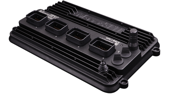
Product photograph: MaxxECU. Used with permission.
MaxxECU produces programmable standalone engine management systems configured with MTune. Product families include universal and vehicle-specific plug-in installations.
Models
- MINI, STREET, SPORT, RACE, RACE H2O and PRO.
- GEN2 SPORT, GEN2 TRACK and GEN2 RACE: newer generation.
- V1: earlier generation, still included in the manufacturer's GEN1 wiring reference.
The manufacturer’s comparison describes supported features; GEN2 RACE product page includes product photographs. Do not assume connectors or capabilities match across versions.
Individual model references
These pages distinguish the original GEN1 units, the discontinued V1 and the newer GEN2 models. Sequential-cylinder figures depend on trigger and engine configuration; injector and ignition counts are separate from general-purpose outputs. Source: MaxxECU comparison and V1 product information.
| Model | Sequential cylinders, maximum | Injector outputs | Ignition outputs |
|---|---|---|---|
| MINI | 4 | 4 high-impedance | 4 |
| STREET | 6 | 6 high-impedance | 6 |
| SPORT | 6 | 6 peak-and-hold | 6 |
| RACE | 8 | 8 peak-and-hold | 8 |
| RACE H2O | 8 | 8 peak-and-hold | 8 |
| PRO | 12 | 16 peak-and-hold | 12 |
| GEN2 SPORT | 6 | 6 peak-and-hold | 6 selectable ignition/GP |
| GEN2 TRACK | 8 | 8 peak-and-hold | 8 selectable ignition/GP |
| GEN2 RACE | 12 | 16 peak-and-hold | 12 selectable ignition/GP |
| V1 | 8 | 8 peak-and-hold | 8 |
RACE H2O has a water-protected case; it is a version of the original RACE, not GEN2 RACE. V1 is discontinued. Revision, kit contents and vehicle-specific adapters must be checked separately.
GEN2 RACE MX1 pinout
Connector 1 (MX1), GEN2 RACE only. Pin numbers are the manufacturer's numbers; consult its connector drawing for orientation. Engine ground goes to the cylinder head; sensor ground must not be connected to engine ground. Manufacturer's full GEN2 pinouts and limitations
| Pin | Function |
|---|---|
| 1–4 | Ignition 1–4 respectively |
| 5–8 | GP outputs 1–4 (ground) respectively |
| 9 | Engine ground |
| 10 | Digital/VR 1 signal + |
| 11 | Digital/VR 1 signal − |
| 12 | Digital/VR 1 power supply |
| 13 | Digital/VR 1 shield |
| 14 | Sensor ground |
| 15 | CAN L |
| 16 | CAN H |
| 17 | GP output 5 (ground) |
| 18 | Digital/VR 2 signal + |
| 19 | Digital/VR 2 signal − |
| 20 | Digital/VR 2 power supply |
| 21 | Digital/VR 2 shield |
| 22 | 5 V supply |
| 23 | Digital/VR 3 signal + |
| 24 | Digital/VR 4 signal + |
| 25 | 12 V supply 1, main ECU supply |
| 26–30 | Analogue inputs 1–5 respectively |
| 31–34 | Injectors 1–4 respectively |
For GEN2 SPORT, TRACK and RACE MX1–MX4 as applicable, use the model pages and the full linked tables. The GEN1 connector tables cover STREET/SPORT/V1/RACE/PRO; pin functions differ. Revision-specific wiring downloads
Confirm the exact ECU, hardware revision and connector orientation before wiring. Configurable functions and electrical limits are model-dependent; consult the linked original diagrams.