Removed text is struck through; added text is highlighted.
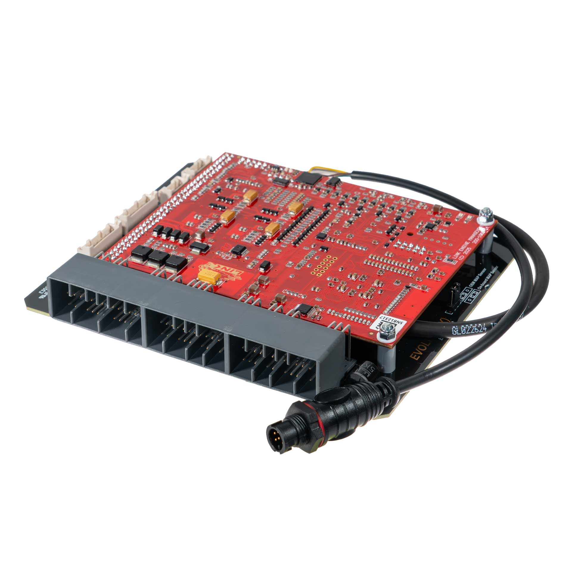
Manufacturer product image of EVO9X application ECU: Link ECU. Permission to republish confirmed by the user.
Link G4X EVO9X is a vehicle-specific programmable plug-in ECU for the Mitsubishi Evo IX application listed in Link's model-specific manuals index. It is an application board, rather than the universal wire-in ECU. Check the exact vehicle, market, engine, original ECU and board part number against the manufacturer's EVO9X installation manual.
Identification and installation
Record the Link model label and revision, donor factory ECU connector and car's engine and year. Plug-in boards connect to particular factory-harness layouts; the family or vehicle name alone does not establish every model-year or transmission combination. The manufacturer manual gives the supported application and any installation or configuration notes for this board.
G4X plug-in platforms offer configurable fuel and ignition control but available channels and features depend on the original header and board. The G4X plug-in general specifications are conditional on the particular application and do not mean every input is brought out to the factory harness.
Pinout and tuning
The EVO9X installation manual is the model-specific source for board pinouts, expansion connections, electrical cautions and startup configuration. Use its connector orientation and the exact board version; do not copy a wire-in ECU pinout onto a factory harness. PCLink and manual downloads; Link manufacturer overview.
EVO9X header and expansion schedulesTranscribed from Link EVOLink IX manual, pages 15–17. Link gives the view into the ECU from the wire side. Pins 36–40 and 69–70 are not listed in the source; “nc” is the manual’s label. Match market and vehicle wiring before connecting.PinECU channelVehicle function1Injector 1Injection2Injector 4Injection3Ignition 5 (Aux)O2 heater4Ignition 6 (Aux)Secondary air solenoid5nc6Ignition 7 (Aux)EGR valve (some models) / high-speed fan relay (EVO 8 JAP)7nc8nc9Injector 2Injection10nc11Ignition 1Ignition cylinders 1 & 412Ignition 2Ignition cylinders 2 & 313nc14Aux 8ISC stepper15Aux 5ISC stepper16nc17nc18Aux 1Engine fan19nc20Injector 5 (Aux)AC relay21Ignition 3 (Aux)Fuel pump relay22Injector 6 (Aux)CE lamp23nc24Injector 3Injection25nc26nc27nc28Aux 7ISC stepper29Aux 6ISC stepper30Ignition 4 (Aux)Condenser fans31Ignition 4 (Aux)Condenser fans32Aux 2VVC solenoid EVO IX only, not VIII JAP33nc34Ground (signal)35nc41Aux 3Wastegate solenoids42+5 V Out43Trig 1Trig 144An Temp 1ECT45TachoFrom Trig 146Ground47+14 V UnregECU power48nc49GroundTPS / MAP50Trig 2Trig 251nc52nc53DI 1Inlet cam position EVO IX only, not VIII JAP54An Volt 5Power steering switch55Aux 12Fuel pump speed relay56Injector 7 (Aux)Intercooler spray relay57Injector 8 (Aux)ECU hold power58Ground59+14 V UnregECU power60nc61An Volt 2MAF signal62An Temp 3MAF IAT63Aux 3Wastegate solenoids64nc65nc66DI 2Intercooler auto switch67DI 7Intercooler manual switch68DI 5Start signal71An Volt 4Front oxygen signal72nc73nc74nc75Ground76nc77nc78An Volt 3TPS signal79nc80DI 3Vehicle speed81nc82nc83DI 4A/C request84nc85nc86nc87nc88DI 8Clutch switch89nc90Ignition 8 (Aux)Intercooler spray lamp91Knock 1Knock92An Volt 1 via jumperMAP factory sensor93nc94nc95nc96An Temp 2IAT EVO IX JAP/US only97nc98nc99DI 6Ignition switch100ncPin 92 factory MAP and the on-board MAP both use An Volt 1 via a selector jumper. The manual repeats condenser fan Ignition 4 at 30/31 and wastegate Aux 3 at 41/63; identify the applicable loom. Injector 8 has hold-power hardware and is unsuitable for injector drive without modification.Expansion connectorPinECU channel1Ground (signal)2+5 V Out3DI 94DI 105Aux 116An Volt 117An Volt 88An Temp 49Ground (signal)10+5 V Out11Aux 912Aux 1013An Volt 614An Volt 715An Volt 916An Volt 10CAN 1 / RS232PinFunction / cable colour1Comms GND (brown)2CAN1 L (green)3CAN1 H (white)4RS232 RX (grey)5RS232 TX (yellow)CAN 2 / OBDPinFunction / cable colour1GND (brown)2CAN2 L (green)3CAN2 H (white)4NC (grey)5+14 V (yellow)Link cautions that connected serial wires can interfere with USB when CAN 1 is used for CAN.
Rendered revisions
Open each version to inspect formatting, tables and photographs.
Revision 1: Link G4X EVO9X plug-in ECU
Link G4X EVO9X is a vehicle-specific programmable plug-in ECU for the Mitsubishi Evo IX application listed in Link's model-specific manuals index. It is an application board, rather than the universal wire-in ECU. Check the exact vehicle, market, engine, original ECU and board part number against the manufacturer's EVO9X installation manual.
Identification and installation
Record the Link model label and revision, donor factory ECU connector and car's engine and year. Plug-in boards connect to particular factory-harness layouts; the family or vehicle name alone does not establish every model-year or transmission combination. The manufacturer manual gives the supported application and any installation or configuration notes for this board.
G4X plug-in platforms offer configurable fuel and ignition control but available channels and features depend on the original header and board. The G4X plug-in general specifications are conditional on the particular application and do not mean every input is brought out to the factory harness.
Pinout and tuning
The EVO9X installation manual is the model-specific source for board pinouts, expansion connections, electrical cautions and startup configuration. Use its connector orientation and the exact board version; do not copy a wire-in ECU pinout onto a factory harness. PCLink and manual downloads; Link manufacturer overview.
Revision 3: Link G4X EVO9X plug-in ECUManufacturer product image of EVO9X application ECU: Link ECU. Permission to republish confirmed by the user.
Link G4X EVO9X is a vehicle-specific programmable plug-in ECU for the Mitsubishi Evo IX application listed in Link's model-specific manuals index. It is an application board, rather than the universal wire-in ECU. Check the exact vehicle, market, engine, original ECU and board part number against the manufacturer's EVO9X installation manual.
Identification and installation
Record the Link model label and revision, donor factory ECU connector and car's engine and year. Plug-in boards connect to particular factory-harness layouts; the family or vehicle name alone does not establish every model-year or transmission combination. The manufacturer manual gives the supported application and any installation or configuration notes for this board.
G4X plug-in platforms offer configurable fuel and ignition control but available channels and features depend on the original header and board. The G4X plug-in general specifications are conditional on the particular application and do not mean every input is brought out to the factory harness.
Pinout and tuning
The EVO9X installation manual is the model-specific source for board pinouts, expansion connections, electrical cautions and startup configuration. Use its connector orientation and the exact board version; do not copy a wire-in ECU pinout onto a factory harness. PCLink and manual downloads; Link manufacturer overview.
EVO9X header and expansion schedules
Transcribed from Link EVOLink IX manual, pages 15–17. Link gives the view into the ECU from the wire side. Pins 36–40 and 69–70 are not listed in the source; “nc” is the manual’s label. Match market and vehicle wiring before connecting.
Pin 92 factory MAP and the on-board MAP both use An Volt 1 via a selector jumper. The manual repeats condenser fan Ignition 4 at 30/31 and wastegate Aux 3 at 41/63; identify the applicable loom. Injector 8 has hold-power hardware and is unsuitable for injector drive without modification.
Expansion connector
Pin
ECU channel
1
Ground (signal)
2
+5 V Out
3
DI 9
4
DI 10
5
Aux 11
6
An Volt 11
7
An Volt 8
8
An Temp 4
9
Ground (signal)
10
+5 V Out
11
Aux 9
12
Aux 10
13
An Volt 6
14
An Volt 7
15
An Volt 9
16
An Volt 10
CAN 1 / RS232
Pin
Function / cable colour
1
Comms GND (brown)
2
CAN1 L (green)
3
CAN1 H (white)
4
RS232 RX (grey)
5
RS232 TX (yellow)
CAN 2 / OBD
Pin
Function / cable colour
1
GND (brown)
2
CAN2 L (green)
3
CAN2 H (white)
4
NC (grey)
5
+14 V (yellow)
Link cautions that connected serial wires can interfere with USB when CAN 1 is used for CAN.