Removed text is struck through; added text is highlighted.
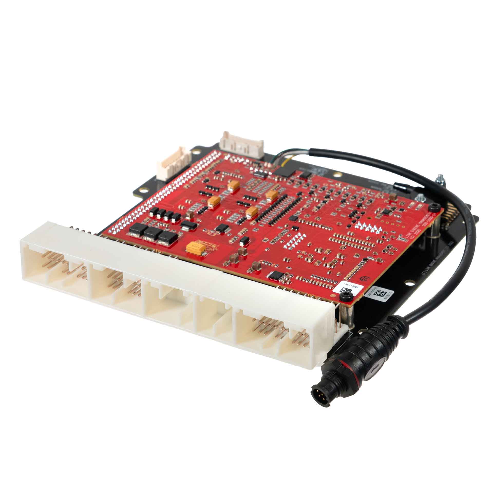
Manufacturer product image of HC20X application ECU: Link ECU. Permission to republish confirmed by the user.
Link G4X HC20X is a vehicle-specific programmable plug-in ECU for the Honda K20 / DC5 application listed in Link's model-specific manuals index. It is an application board, rather than the universal wire-in ECU. Check the exact vehicle, market, engine, original ECU and board part number against the manufacturer's HC20X installation manual.
Identification and installation
Record the Link model label and revision, donor factory ECU connector and car's engine and year. Plug-in boards connect to particular factory-harness layouts; the family or vehicle name alone does not establish every model-year or transmission combination. The manufacturer manual gives the supported application and any installation or configuration notes for this board.
G4X plug-in platforms offer configurable fuel and ignition control but available channels and features depend on the original header and board. The G4X plug-in general specifications are conditional on the particular application and do not mean every input is brought out to the factory harness.
Pinout and tuning
The HC20X installation manual is the model-specific source for board pinouts, expansion connections, electrical cautions and startup configuration. Use its connector orientation and the exact board version; do not copy a wire-in ECU pinout onto a factory harness. PCLink and manual downloads; Link manufacturer overview.
Manufacturer connector schedulesFrom Link's HC20X installation manual. Link describes the view as looking into the ECU from the wire side. A dash reproduces an unspecified source field; nc is Link's label. Confirm the vehicle and board revision before use. This guide identifies the DC5 Integra Type R and compatible Civic generation 7 applications. A/C request is received over K-Line on CAN DI 1. Link says Aux 15 must be on (active low) for correct operation. The internal MAP input is selected with a jumper.Factory main headerFactory pinLink ECU channelFactory functionA1Injector 7 (Aux)NB O2 Heater ControlE1Aux 1Fuel Pump RelayA2+14V ECU Power—E2An Volt 7Secondary NB O2 SignalA3+14V ECU Power—E3Ground—A4Ground (Power)—E4Ground (Signal)—A5Ground (Power)—E5+5V Out—A6An Volt 11NB O2 SignalE6Injector 8 (Aux)Secondary NB O2 Heater ControlA7Trigger 1Crank Position SensorE7Main RelayControlled by Ignition Switch (E9)A8An Volt 10Intake Runner Position, (2002-2004 RSX K20A3 and 2002-2004 CRV K24A1 only)E8Injector 5 (Aux)O2 Heater Control Relay (Controls +12V supply to both NB O2 heaters)A9Knock 1Knock SensorE9DI10Ignition Switch InputA10Ground (Signal)—E10nc—A11Ground (Signal)—E11nc—A12Aux 5Idle Solenoid (IACV)E12nc—A13An Volt 12EGR Position, (2001- 2005 Civic D17A2/D17A6 only)E13nc—A14Injector 6 (Aux)Secondary O2 Heater, (2001-2005 Civic D17A2/D17A6 only)E14An Volt 9Fuel Tank PressureA15An Volt 2TPSE15An Volt 8Electrical LoadA16Ground (Signal)Primary O2 Signal GroundE16DI 3PS Pressure SwitchA17nc—E17nc—A18DI 2Vehicle SpeedE18Ignition 6 (Aux)AC ClutchA19An Volt 1Factory MAP Sensor (Via Jumper)E19nc—A20+5V Out—E20Aux 12EVAP emissions bypass solenoid valveA21+5V Out—E21Aux 11EVAP emmisions canister vent shut valveA22nc—E22DI 4Brake Pedal SwitchA23Ground—E23nc—A24Ground—E24KLineCommunicates with vehicle (temp gauge, ac switch, batt light)A25DI 1VVT Cam Position (K Series)E25nc—A26Trigger 2Cam Sync SensorE26Aux 3TachoA27Ignition 4IgnitionE27KLineCommunicates with the ImmobiliserA28Ignition 3IgnitionE28nc—A29Ignition 2IgnitionE29nc—A30Ignition 1IgnitionE30nc—A31nc—E31Ignition 5 (Aux)CE LightB1+14V OutVTC Oil Control Sol +veB2Injector 4InjectionB3Injector 3InjectionB4Injector 2InjectionB5Injector 1InjectionB6Aux 13Radiator Fan RelayB7Aux 4Reverse Lockout Solenoid (K20A2)B8An Temp 1ECTB9DI 5VTEC Oil Pressure SwitchB10nc—B11nc—B12nc—B13nc—B14nc—B15Aux 14VTEC Solenoid (Drives High Side)B16nc—B17An Temp 2IATB18Aux 8Alternator ControlB19nc—B20nc—B21Ignition 8 (Aux)Evap PurgeB22Ignition 7 (Aux)Intake Runner ControlB23Aux 2VTC Oil Control Sol -veB24nc—Expansion connectorPositionLink ECU channelFunctionExpansion 1Ground (Signal)—Expansion 2+5V Out—Expansion 3Aux 9—Expansion 4Aux 10—Expansion 5An Volt 4—Expansion 6An Volt 5—Expansion 7An Volt 6—Expansion 8An Volt 3—Expansion 9An Temp 4—Expansion 10An Temp 3—Expansion 11DI 9—Expansion 12DI 8—Expansion 13DI 7—Expansion 14DI 6—Expansion 15Aux 7—Expansion 16Aux 6—Other connectionsPositionLink ECU channelFunctionOn-Board MAPAn Volt 1Jumper connects An Volt 1 to this or A19E-Throttle RelayAux 16Only used when adding E- ThrottleOn-Board power RelayAux 15Used to prevent back feedingCAN ConnectorPinFunctionWire colour1Comms GNDBrown2CAN LGreen3CAN HWhite4+14VYellow
Rendered revisions
Open each version to inspect formatting, tables and photographs.
Revision 1: Link G4X HC20X plug-in ECU
Link G4X HC20X is a vehicle-specific programmable plug-in ECU for the Honda K20 / DC5 application listed in Link's model-specific manuals index. It is an application board, rather than the universal wire-in ECU. Check the exact vehicle, market, engine, original ECU and board part number against the manufacturer's HC20X installation manual.
Identification and installation
Record the Link model label and revision, donor factory ECU connector and car's engine and year. Plug-in boards connect to particular factory-harness layouts; the family or vehicle name alone does not establish every model-year or transmission combination. The manufacturer manual gives the supported application and any installation or configuration notes for this board.
G4X plug-in platforms offer configurable fuel and ignition control but available channels and features depend on the original header and board. The G4X plug-in general specifications are conditional on the particular application and do not mean every input is brought out to the factory harness.
Pinout and tuning
The HC20X installation manual is the model-specific source for board pinouts, expansion connections, electrical cautions and startup configuration. Use its connector orientation and the exact board version; do not copy a wire-in ECU pinout onto a factory harness. PCLink and manual downloads; Link manufacturer overview.
Revision 3: Link G4X HC20X plug-in ECUManufacturer product image of HC20X application ECU: Link ECU. Permission to republish confirmed by the user.
Link G4X HC20X is a vehicle-specific programmable plug-in ECU for the Honda K20 / DC5 application listed in Link's model-specific manuals index. It is an application board, rather than the universal wire-in ECU. Check the exact vehicle, market, engine, original ECU and board part number against the manufacturer's HC20X installation manual.
Identification and installation
Record the Link model label and revision, donor factory ECU connector and car's engine and year. Plug-in boards connect to particular factory-harness layouts; the family or vehicle name alone does not establish every model-year or transmission combination. The manufacturer manual gives the supported application and any installation or configuration notes for this board.
G4X plug-in platforms offer configurable fuel and ignition control but available channels and features depend on the original header and board. The G4X plug-in general specifications are conditional on the particular application and do not mean every input is brought out to the factory harness.
Pinout and tuning
The HC20X installation manual is the model-specific source for board pinouts, expansion connections, electrical cautions and startup configuration. Use its connector orientation and the exact board version; do not copy a wire-in ECU pinout onto a factory harness. PCLink and manual downloads; Link manufacturer overview.
Manufacturer connector schedules
From Link's HC20X installation manual. Link describes the view as looking into the ECU from the wire side. A dash reproduces an unspecified source field; nc is Link's label. Confirm the vehicle and board revision before use. This guide identifies the DC5 Integra Type R and compatible Civic generation 7 applications. A/C request is received over K-Line on CAN DI 1. Link says Aux 15 must be on (active low) for correct operation. The internal MAP input is selected with a jumper.