Earlier model: Original EMU
Individual model references
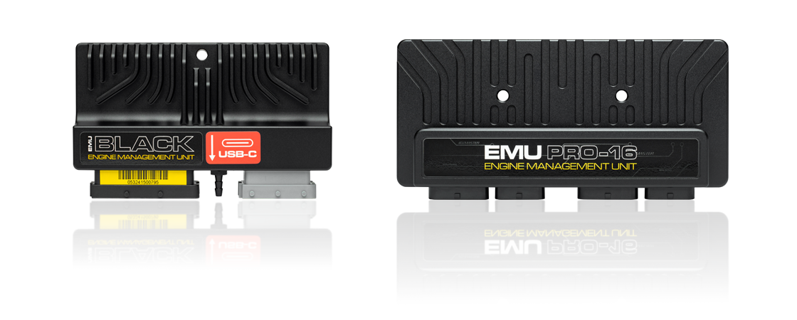
ECUMaster's standalone engine management families include EMU Classic, EMU Black, EMU Pro-8 and EMU Pro-16. The manufacturer provides a model comparison with product photographs and current downloads and application-specific pinouts.
Models
- EMU Classic: 48 pins across two FCI connectors; six high-impedance injector outputs. Drive-by-wire requires an external module.
- EMU Black: 63 pins across two FCI connectors; up to eight high-impedance injector outputs, including two shared auxiliary outputs; one drive-by-wire controller. There are also application-specific plug-in units.
- EMU Pro-8: 96 pins across three AMP Superseal connectors; eight peak-and-hold injector outputs.
- EMU Pro-16: 120 pins across four AMP Superseal connectors; 16 peak-and-hold injector outputs.
Pro-8 and Pro-16 direct-injection applications require a separate GDI driver. Figures are from the manufacturer comparison. Different plug-in models have vehicle-specific connections; do not apply the universal wire-in diagrams to them. DET3 is a piggyback controller and is outside this standalone list.
Model guide and comparison
ECUMaster's original EMU was followed by the EMU Classic, then the Black and the separate Pro hardware and software platform. ECU Master USA describes the Classic as a revised EMU using the same firmware and software, with a revised enclosure and electronics. The manufacturer’s Black V3 migration guide describes Black as originally based on Classic architecture and the Pro as a new platform. Version and firmware selection matter when opening or moving calibrations. EMU Classic introduction · Black V3 migration guide.
| System | ECU and installation identity | Outputs and onboard features | Documents |
|---|---|---|---|
| Original EMU | Earlier programmable EMU preceding Classic. Record the label and connector rather than assuming a Classic enclosure. | Its successor uses the same EMU firmware and software according to ECUMaster USA. Older units and optional CAN arrangements should be identified individually. | Classic and original EMU differences |
| EMU Classic | Universal port-injection ECU; two 24-way FCI connectors. Built-in MAP sensor and a direct LSU 4.2 wideband input; CAN needs the external module. | Six high-impedance injector outputs and six ignition outputs. The comparison lists external hardware for electronic throttle. The Classic page lists two K-type EGT inputs and flex-fuel input options. | Classic specifications and software · Classic pinout |
| EMU Black | Universal port-injection ECU; one 39-way black and one 24-way grey FCI connector. Built-in 4-bar MAP sensor and LSU 4.2 or 4.9 wideband controller, plus CAN. | Six dedicated high-impedance injector outputs; two auxiliary outputs can be reassigned to give up to eight. Six ignition outputs and one electronic throttle controller. Two K-type EGT inputs; two knock inputs. | Black specifications · Black pinout |
| EMU Pro-8 | Three AMP Superseal connectors, 96 positions; IP65 enclosure. The manufacturer positions it for engines with up to eight cylinders. | Eight peak-and-hold injector outputs, eight active/passive ignition outputs, two internal LSU 4.9 controllers, two electronic throttle controllers, two CAN buses and LIN. Direct injection requires the separate GDI Driver. | Pro product documentation · Pro-8 pinout v1.0 |
| EMU Pro-16 | Four AMP Superseal connectors, 120 positions; IP65 enclosure and larger I/O complement. | Sixteen peak-and-hold injector outputs; comparison lists up to 12 active or 10 passive coils, two internal LSU 4.9 controllers, two throttle controllers, two CAN buses and LIN. GDI requires a separate driver. | Pro-16 pinout v1.1 · Pro hardware manual |
Specification comparison: ECUMaster ECU comparison. The listed output counts do not mean all functions can be used simultaneously: shared outputs, driver type and wiring must match the installation. For Pro-16 pinout v1.1, the manufacturer specifies board revision F or newer and the serial threshold on the document. Check the actual board and the latest manual.
EMU Black vehicle-specific plug-in units
These are complete Black-based ECUs in application-specific enclosures, not separate adapters or a promise of interchangeability between engine codes. ECUMaster lists the following configurations and provides application notes, pinouts or base maps for several of them. Check ECU plug, engine code, gearbox, emissions equipment and intended vehicle against the current manufacturer documentation. ECUMaster plug-in catalogue · manufacturer downloads.
- MINI Cooper R50 and MINI Cooper S R53.
- Lotus 2ZR-FE and 2ZZ-GE drive-by-wire configurations.
- Volkswagen/Audi 1.8T BAM, ARX, ARY, AUM and AUQ.
- Volkswagen R32 VR6 BFH and BUB.
- Audi RS4 ASJ/AZR and Nissan 200SX S13 SR20DET appear on the manufacturer page marked not yet available; do not assume they can be ordered or that their pinouts are released.
Interconnectors and expansion
ECUMaster also lists interconnector looms that adapt a factory harness to a separate universal EMU Classic or Black. They are distinct from the complete Black plug-in ECU range. Documented applications include BMW M50B25 DME 3.1 and M50B25TU DME 3.3.1; Audi 2.2 3B, AAN and ABY and B5 2.7 biturbo; Fiat 500 Abarth 1.4T; Ford Focus RS/ST Mk2; Mitsubishi Evo 4–8; Nissan 64- and 76-pin applications; Subaru Impreza MY96–98; Toyota 1JZ-GTE, 2JZ-GTE non-VVTi, 3S-GTE ST185/ST205/ST215 and MR2 SW20; and listed VAG 1.8T BAM and R32 BFH. Some historical adapters are marked discontinued. Interconnector application and manual list.
The Pro GDI Driver is a separate injector-driver module rather than an ECU, and the DET3 is an additional piggyback tuning device, not a member of the standalone EMU ECU family. A base map or an interconnector listing does not establish full function for every wiring variant. Pro GDI information · product family.
Software, control and identification
The manufacturer publishes separate Classic, Black and Pro software, manuals and firmware in its download centre. The Black V3 migration guide describes a software transition and warns that migration involves additional configuration: keep an original project and check the manufacturer's conversion procedure instead of assuming all data is portable. The Pro uses CAN-to-PC hardware rather than a direct ECU USB connection. Software functions and firmware versions change, so record ECU serial, firmware, software version, connector variant and current calibration.
Black and Classic provide direct wideband sensing within the combinations stated above; the Pro has two internal LSU 4.9 controllers and supports external logging to USB. Base maps are starting configurations, not evidence that a particular harness or injector setup is correct. Match the numbered pins, assigned inputs and outputs, trigger pattern and electrical characteristics before powering actuators. Pro specification · Black FAQ.
EMU Black pinout
Universal EMU Black wire-in ECU only. Connector colour and pin numbers follow ECUMaster's EMU Black pinout PDF; refer to the manufacturer's drawings for connector view and orientation, electrical limits, sensor wiring and setup. Shared outputs depend on calibration.
Black 39-pin connector
| Pin | Function |
|---|---|
| 1 | Ignition coil 5 |
| 2 | EGT input 1 |
| 3 | Knock sensor input 1 |
| 4 | Analogue input 2 |
| 5 | Coolant temperature input |
| 6 | Wideband oxygen Vs |
| 7 | Cam sync input 2 |
| 8 | Primary trigger |
| 9 | Flex fuel input |
| 10 | Switch input 1 |
| 11 | RS232 TXD |
| 12 | CAN high |
| 13 | Battery +12 V |
| 14 | Ignition coil 4 |
| 15 | EGT input 2 |
| 16 | Knock sensor input 2 |
| 17 | Analogue input 3 |
| 18 | Throttle position input |
| 19 | Wideband oxygen Ip |
| 20 | Vehicle speed input |
| 21 | Cam sync input 1 |
| 22 | Wideband oxygen Rcal |
| 23 | Switch input 2 |
| 24 | RS232 RXD |
| 25 | CAN low |
| 26 | 5 V supply |
| 27 | Power ground |
| 28 | ECU ground |
| 29 | Sensor ground |
| 30 | Analogue input 4 |
| 31 | Analogue input 1 |
| 32 | Intake air temperature input |
| 33 | Wideband oxygen VGND |
| 34 | 5 V supply |
| 35 | Analogue input 5 |
| 36 | Switch input 3 |
| 37 | Analogue input 6 |
| 38 | Sensor ground |
| 39 | Sensor ground |
Grey 24-pin connector
| Pin | Function |
|---|---|
| 1 | Ignition coil 6 |
| 2 | H-bridge 1 winding A |
| 3 | H-bridge 2 winding A |
| 4 | AUX 6 |
| 5 | AUX 3 |
| 6 | Injector 4 |
| 7 | Injector 1 |
| 8 | Ignition coil 1 |
| 9 | Ignition coil 3 |
| 10 | H-bridge 1 winding B |
| 11 | H-bridge 2 winding B |
| 12 | AUX 5 |
| 13 | AUX 2 / injector 8 |
| 14 | Injector 5 |
| 15 | Injector 2 |
| 16 | Ignition coil 2 |
| 17 | Power ground |
| 18 | Ignition +12 V |
| 19 | Wideband oxygen heater |
| 20 | AUX 4 / tacho |
| 21 | AUX 1 / injector 7 |
| 22 | Injector 6 |
| 23 | Injector 3 |
| 24 | Power ground |
Other model diagrams and manuals
- EMU Classic pinout
- EMU Pro-8 pinout v1.0
- EMU Pro-16 pinout v1.1 — document specifies board revision F or newer and serial 101-2242-xxxxx and higher.
- Downloads including plug-in ECU diagrams
- Hardware and software manuals