MaxxECU GEN2 TRACK — New-generation ECU for up to eight sequential cylinders, with IP68-rated enclosure and dual wideband and knock inputs. MaxxECU product information.
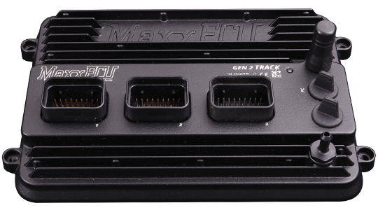
Model identification and capabilities
TRACK has eight peak-and-hold injector/GP outputs, eight selectable ignition/GP outputs, 16 analogue inputs and six VR/Hall pulse inputs. The manufacturer specifies dual CAN, a 550 kPa absolute MAP sensor, Wi-Fi, Bluetooth and USB-C. It lists support for LSU 5.2, 4.9 and 4.2 sensors. Manufacturer specification; MaxxECU model comparison.
| Sequential cylinders, maximum | 8 |
|---|---|
| Injector outputs | 8 peak-and-hold |
| Ignition outputs | 8 selectable ignition/GP |
| Configuration | MTune; check the release appropriate to the ECU and hardware revision |
Identification and installation
GEN2 connector numbers and assignments are not the GEN1 RACE pinout. TRACK differs from GEN2 RACE at several MX3 positions, including CAN 2 and pulse inputs; use the TRACK column.
Record the model label, serial number, hardware revision, firmware, connector keying and loom. Outputs can be assigned or share functions; supported functions also depend on available I/O and software configuration. The figure in the comparison is a controller capability, not proof of compatibility with a particular engine or vehicle.
Connectors and pinout
The following positions follow the TRACK column in MaxxECU's GEN2 wiring reference. Blank values in model-specific columns inherit the adjacent shared function; explicitly unavailable positions are retained. Check the physical connector drawing before wiring.
Connector MX1
From the manufacturer's GEN2 TRACK connector reference; establish the connector view and check wiring and current limits in the original.
| Pin | Function | Note |
|---|---|---|
| 1 | Ignition 1 | |
| 2 | Ignition 2 | |
| 3 | Ignition 3 | |
| 4 | Ignition 4 | |
| 5 | GP out 1 (GND) | |
| 6 | GP out 2 (GND) | |
| 7 | GP out 3 (GND) | |
| 8 | GP out 4 (GND) | |
| 9 | Engine gnd | To engine cylinder head. |
| 10 | Digital/VR 1 (PULSE) SIGNAL + | |
| 11 | Digital/VR 1 (PULSE) SIGNAL - | |
| 12 | Digital/VR 1 (PULSE) POWER SUPPLY | |
| 13 | Digital/VR 1 (PULSE) SHIELD | |
| 14 | SENSOR GND | Must NOT be connected to engine GND |
| 15 | CAN L | |
| 16 | CAN H | |
| 17 | GP out 5 (GND) | |
| 18 | Digital/VR 2 (PULSE) SIGNAL + | |
| 19 | Digital/VR 2 (PULSE) SIGNAL - | |
| 20 | Digital/VR 2 (PULSE) POWER SUPPLY | |
| 21 | Digital/VR 2 (PULSE) SHIELD | |
| 22 | 5V power supply | |
| 23 | Digital/VR 3 (PULSE) SIGNAL + | |
| 24 | Digital/VR 4 (PULSE) SIGNAL + | |
| 25 | 12V supply 1 | Main ECU supply. |
| 26 | AIN 1 | |
| 27 | AIN 2 | |
| 28 | AIN 3 | |
| 29 | AIN 4 | |
| 30 | AIN 5 | |
| 31 | INJECTOR 1 | |
| 32 | INJECTOR 2 | |
| 33 | INJECTOR 3 | |
| 34 | INJECTOR 4 |
Connector MX2
From the manufacturer's GEN2 TRACK connector reference; establish the connector view and check wiring and current limits in the original.
| Pin | Function | Note |
|---|---|---|
| 1 | Ignition 5 | |
| 2 | Ignition 6 | |
| 3 | GP out 6 (GND) | |
| 4 | AIN 6 | |
| 5 | AIN 7 | |
| 6 | AIN 8 | |
| 7 | GP out 13 (H-BRIDGE 1) | |
| 8 | GP out 14 (H-BRIDGE 1) | |
| 9 | Engine gnd | To engine cylinder head. |
| 10 | WBO2 Sensor 1 VS | |
| 11 | WBO2 Sensor 1 COM/VREF | |
| 12 | GP OUT 7 / WBO2 Sensor 1 H- | |
| 13 | AIN 9 | |
| 14 | AIN 10 | |
| 15 | AIN 11 | |
| 16 | AIN 12 | |
| 17 | Not available | |
| 18 | WBO2 sensor 1 RCAL | |
| 19 | WBO2 sensor 1 IP | |
| 20 | 12V WBO2 sensor 1 H+ | |
| 21 | WBO2 sensor 1 SHIELD | |
| 22 | Not available | |
| 23 | Not available | |
| 24 | 12V supply 3 | Used for ignition key or to power the internal RTC |
| 25 | 12V supply 2 | Must be wired if 12V driving output exceeds 10A |
| 26 | KNOCK1 SHIELD | |
| 27 | KNOCK 1- | |
| 28 | KNOCK 1+ | |
| 29 | KNOCK 2 SHIELD | |
| 30 | KNOCK 2- | |
| 31 | KNOCK 2+ | |
| 32 | Not available | |
| 33 | INJECTOR 5 | |
| 34 | INJECTOR 6 |
Connector MX3
From the manufacturer's GEN2 TRACK connector reference; establish the connector view and check wiring and current limits in the original.
| Pin | Function | Note |
|---|---|---|
| 1 | GP out 15 (H-BRIDGE 2) | |
| 2 | GP out 16 (H-BRIDGE 2) | |
| 3 | Ignition 7 | |
| 4 | Ignition 8 | |
| 5 | Not available | |
| 6 | Not available | |
| 7 | Not available | |
| 8 | Not available | |
| 9 | Engine gnd | To engine cylinder head. |
| 10 | WBO2 sensor 2 VS | |
| 11 | WBO2 sensor 2 COM/VREF | |
| 12 | GP Out 8 (GND) / WBO2 Sensor 2 H- | |
| 13 | Not available | |
| 14 | GP OUT 9 (12V) | |
| 15 | GP OUT 10 (12V) | |
| 16 | GP OUT 11 (12V) | |
| 17 | GP OUT 12 (12V) | |
| 18 | WBO2 sensor 2 RCAL | |
| 19 | WBO2 sensor 2 IP | |
| 20 | 12V WBO2 sensor 2 �(H+) | |
| 21 | Digital/VR 5 (PULSE) SIGNAL + | |
| 22 | Digital/VR 5 (PULSE) SIGNAL - | |
| 23 | Digital/VR 5 (PULSE) SHIELD | |
| 24 | CAN 2 L | |
| 25 | CAN 2 H | |
| 26 | Digital/VR 6 (PULSE) SIGNAL + | |
| 27 | Digital/VR 6 (PULSE) SIGNAL - | |
| 28 | Digital/VR 6 (PULSE) SHIELD | |
| 29 | INJECTOR 7 | |
| 30 | INJECTOR 8 | |
| 31 | Not available | |
| 32 | Not available | |
| 33 | Not available | |
| 34 | Not available |
Software and further documents
- MaxxECU GEN2 TRACK: product information
- Model wiring and pinout reference
- MTune, quick-start guides and revision-specific wiring downloads
- MaxxECU family overview
Sources reviewed 17 November 2026.