Removed text is struck through; added text is highlighted.
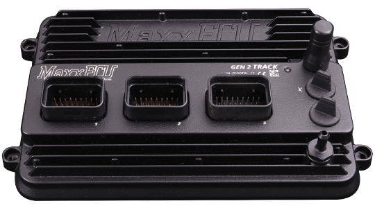
MaxxECU GEN2 TRACK — New-generation ECU for up to eight sequential cylinders, with IP68-rated enclosure and dual wideband and knock inputs. MaxxECU product information.
MaxxECU GEN2 TRACK, manufacturer product image: MaxxECU. Used with permission.
Model identification and capabilities
TRACK has eight peak-and-hold injector/GP outputs, eight selectable ignition/GP outputs, 16 analogue inputs and six VR/Hall pulse inputs. The manufacturer specifies dual CAN, a 550 kPa absolute MAP sensor, Wi-Fi, Bluetooth and USB-C. It lists support for LSU 5.2, 4.9 and 4.2 sensors. Manufacturer specification; MaxxECU model comparison.
Sequential cylinders, maximum8Injector outputs8 peak-and-holdIgnition outputs8 selectable ignition/GPConfigurationMTune; check the release appropriate to the ECU and hardware revision
Identification and installation
GEN2 connector numbers and assignments are not the GEN1 RACE pinout. TRACK differs from GEN2 RACE at several MX3 positions, including CAN 2 and pulse inputs; use the TRACK column.
Record the model label, serial number, hardware revision, firmware, connector keying and loom. Outputs can be assigned or share functions; supported functions also depend on available I/O and software configuration. The figure in the comparison is a controller capability, not proof of compatibility with a particular engine or vehicle.
Connectors and pinoutThe following positions follow the TRACK column in MaxxECU's GEN2 wiring reference. Blank values in model-specific columns inherit the adjacent shared function; explicitly unavailable positions are retained. Check the physical connector drawing before wiring.Connector MX1From the manufacturer's GEN2 TRACK connector reference; establish the connector view and check wiring and current limits in the original.PinFunctionNote1Ignition 12Ignition 23Ignition 34Ignition 45GP out 1 (GND)6GP out 2 (GND)7GP out 3 (GND)8GP out 4 (GND)9Engine gndTo engine cylinder head.10Digital/VR 1 (PULSE) SIGNAL +11Digital/VR 1 (PULSE) SIGNAL -12Digital/VR 1 (PULSE) POWER SUPPLY13Digital/VR 1 (PULSE) SHIELD14SENSOR GNDMust NOT be connected to engine GND15CAN L16CAN H17GP out 5 (GND)18Digital/VR 2 (PULSE) SIGNAL +19Digital/VR 2 (PULSE) SIGNAL -20Digital/VR 2 (PULSE) POWER SUPPLY21Digital/VR 2 (PULSE) SHIELD225V power supply23Digital/VR 3 (PULSE) SIGNAL +24Digital/VR 4 (PULSE) SIGNAL +2512V supply 1Main ECU supply.26AIN 127AIN 228AIN 329AIN 430AIN 531INJECTOR 132INJECTOR 233INJECTOR 334INJECTOR 4Connector MX2From the manufacturer's GEN2 TRACK connector reference; establish the connector view and check wiring and current limits in the original.PinFunctionNote1Ignition 52Ignition 63GP out 6 (GND)4AIN 65AIN 76AIN 87GP out 13 (H-BRIDGE 1)8GP out 14 (H-BRIDGE 1)9Engine gndTo engine cylinder head.10WBO2 Sensor 1 VS11WBO2 Sensor 1 COM/VREF12GP OUT 7 / WBO2 Sensor 1 H-13AIN 914AIN 1015AIN 1116AIN 1217Not available18WBO2 sensor 1 RCAL19WBO2 sensor 1 IP2012V WBO2 sensor 1 H+21WBO2 sensor 1 SHIELD22Not available23Not available2412V supply 3Used for ignition key or to power the internal RTC2512V supply 2Must be wired if 12V driving output exceeds 10A26KNOCK1 SHIELD27KNOCK 1-28KNOCK 1+29KNOCK 2 SHIELD30KNOCK 2-31KNOCK 2+32Not available33INJECTOR 534INJECTOR 6Connector MX3From the manufacturer's GEN2 TRACK connector reference; establish the connector view and check wiring and current limits in the original.PinFunctionNote1GP out 15 (H-BRIDGE 2)2GP out 16 (H-BRIDGE 2)3Ignition 74Ignition 85Not available6Not available7Not available8Not available9Engine gndTo engine cylinder head.10WBO2 sensor 2 VS11WBO2 sensor 2 COM/VREF12GP Out 8 (GND) / WBO2 Sensor 2 H-13Not available14GP OUT 9 (12V)15GP OUT 10 (12V)16GP OUT 11 (12V)17GP OUT 12 (12V)18WBO2 sensor 2 RCAL19WBO2 sensor 2 IP2012V WBO2 sensor 2 �(H+)21Digital/VR 5 (PULSE) SIGNAL +22Digital/VR 5 (PULSE) SIGNAL -23Digital/VR 5 (PULSE) SHIELD24CAN 2 L25CAN 2 H26Digital/VR 6 (PULSE) SIGNAL +27Digital/VR 6 (PULSE) SIGNAL -28Digital/VR 6 (PULSE) SHIELD29INJECTOR 730INJECTOR 831Not available32Not available33Not available34Not availableConnector and pinoutSelected GEN2 TRACK MX3 positions. The manufacturer’s table uses a separate TRACK column; consult the full diagram for connector orientation and remaining positions. These positions are manufacturer-labelled ECU functions, not an assurance that a particular loom or calibration uses them. Exact wiring and connector reference.PositionFunction3Ignition 74Ignition 89Engine ground10Wideband 2 VS11Wideband 2 COM/VREF12GPO 8 / wideband 2 heater negative18Wideband 2 RCAL19Wideband 2 IP20Wideband 2 heater positive 12 V21–23Pulse input 5 signal +, signal −, shield24CAN 2 low25CAN 2 high26–28Pulse input 6 signal +, signal −, shield29–30Injector 7, injector 8 respectivelyConsult the full diagram for wiring, grounds, supply fuses, driver limits, connector orientation and remaining positions. Sensor grounds and power grounds have different purposes; follow the matching manual.
Software and further documents
MaxxECU GEN2 TRACK: product informationModel wiring and pinout referenceMTune, quick-start guides and revision-specific wiring downloadsMaxxECU family overview
Sources reviewed 17 November 2026.
Rendered revisions
Open each version to inspect formatting, tables and photographs.
Revision 1: MaxxECU GEN2 TRACK
MaxxECU GEN2 TRACK — New-generation ECU for up to eight sequential cylinders, with IP68-rated enclosure and dual wideband and knock inputs. MaxxECU product information.
MaxxECU GEN2 TRACK, manufacturer product image: MaxxECU. Used with permission.
Model identification and capabilities
TRACK has eight peak-and-hold injector/GP outputs, eight selectable ignition/GP outputs, 16 analogue inputs and six VR/Hall pulse inputs. The manufacturer specifies dual CAN, a 550 kPa absolute MAP sensor, Wi-Fi, Bluetooth and USB-C. It lists support for LSU 5.2, 4.9 and 4.2 sensors. Manufacturer specification; MaxxECU model comparison.
Sequential cylinders, maximum
8
Injector outputs
8 peak-and-hold
Ignition outputs
8 selectable ignition/GP
Configuration
MTune; check the release appropriate to the ECU and hardware revision
Identification and installation
GEN2 connector numbers and assignments are not the GEN1 RACE pinout. TRACK differs from GEN2 RACE at several MX3 positions, including CAN 2 and pulse inputs; use the TRACK column.
Record the model label, serial number, hardware revision, firmware, connector keying and loom. Outputs can be assigned or share functions; supported functions also depend on available I/O and software configuration. The figure in the comparison is a controller capability, not proof of compatibility with a particular engine or vehicle.
Connector and pinout
Selected GEN2 TRACK MX3 positions. The manufacturer’s table uses a separate TRACK column; consult the full diagram for connector orientation and remaining positions. These positions are manufacturer-labelled ECU functions, not an assurance that a particular loom or calibration uses them. Exact wiring and connector reference.
Position
Function
3
Ignition 7
4
Ignition 8
9
Engine ground
10
Wideband 2 VS
11
Wideband 2 COM/VREF
12
GPO 8 / wideband 2 heater negative
18
Wideband 2 RCAL
19
Wideband 2 IP
20
Wideband 2 heater positive 12 V
21–23
Pulse input 5 signal +, signal −, shield
24
CAN 2 low
25
CAN 2 high
26–28
Pulse input 6 signal +, signal −, shield
29–30
Injector 7, injector 8 respectively
Consult the full diagram for wiring, grounds, supply fuses, driver limits, connector orientation and remaining positions. Sensor grounds and power grounds have different purposes; follow the matching manual.
MaxxECU GEN2 TRACK — New-generation ECU for up to eight sequential cylinders, with IP68-rated enclosure and dual wideband and knock inputs. MaxxECU product information.
MaxxECU GEN2 TRACK, manufacturer product image: MaxxECU. Used with permission.
Model identification and capabilities
TRACK has eight peak-and-hold injector/GP outputs, eight selectable ignition/GP outputs, 16 analogue inputs and six VR/Hall pulse inputs. The manufacturer specifies dual CAN, a 550 kPa absolute MAP sensor, Wi-Fi, Bluetooth and USB-C. It lists support for LSU 5.2, 4.9 and 4.2 sensors. Manufacturer specification; MaxxECU model comparison.
Sequential cylinders, maximum
8
Injector outputs
8 peak-and-hold
Ignition outputs
8 selectable ignition/GP
Configuration
MTune; check the release appropriate to the ECU and hardware revision
Identification and installation
GEN2 connector numbers and assignments are not the GEN1 RACE pinout. TRACK differs from GEN2 RACE at several MX3 positions, including CAN 2 and pulse inputs; use the TRACK column.
Record the model label, serial number, hardware revision, firmware, connector keying and loom. Outputs can be assigned or share functions; supported functions also depend on available I/O and software configuration. The figure in the comparison is a controller capability, not proof of compatibility with a particular engine or vehicle.
Connectors and pinout
The following positions follow the TRACK column in MaxxECU's GEN2 wiring reference. Blank values in model-specific columns inherit the adjacent shared function; explicitly unavailable positions are retained. Check the physical connector drawing before wiring.
Connector MX1
From the manufacturer's GEN2 TRACK connector reference; establish the connector view and check wiring and current limits in the original.
Pin
Function
Note
1
Ignition 1
2
Ignition 2
3
Ignition 3
4
Ignition 4
5
GP out 1 (GND)
6
GP out 2 (GND)
7
GP out 3 (GND)
8
GP out 4 (GND)
9
Engine gnd
To engine cylinder head.
10
Digital/VR 1 (PULSE) SIGNAL +
11
Digital/VR 1 (PULSE) SIGNAL -
12
Digital/VR 1 (PULSE) POWER SUPPLY
13
Digital/VR 1 (PULSE) SHIELD
14
SENSOR GND
Must NOT be connected to engine GND
15
CAN L
16
CAN H
17
GP out 5 (GND)
18
Digital/VR 2 (PULSE) SIGNAL +
19
Digital/VR 2 (PULSE) SIGNAL -
20
Digital/VR 2 (PULSE) POWER SUPPLY
21
Digital/VR 2 (PULSE) SHIELD
22
5V power supply
23
Digital/VR 3 (PULSE) SIGNAL +
24
Digital/VR 4 (PULSE) SIGNAL +
25
12V supply 1
Main ECU supply.
26
AIN 1
27
AIN 2
28
AIN 3
29
AIN 4
30
AIN 5
31
INJECTOR 1
32
INJECTOR 2
33
INJECTOR 3
34
INJECTOR 4
Connector MX2
From the manufacturer's GEN2 TRACK connector reference; establish the connector view and check wiring and current limits in the original.
Pin
Function
Note
1
Ignition 5
2
Ignition 6
3
GP out 6 (GND)
4
AIN 6
5
AIN 7
6
AIN 8
7
GP out 13 (H-BRIDGE 1)
8
GP out 14 (H-BRIDGE 1)
9
Engine gnd
To engine cylinder head.
10
WBO2 Sensor 1 VS
11
WBO2 Sensor 1 COM/VREF
12
GP OUT 7 / WBO2 Sensor 1 H-
13
AIN 9
14
AIN 10
15
AIN 11
16
AIN 12
17
Not available
18
WBO2 sensor 1 RCAL
19
WBO2 sensor 1 IP
20
12V WBO2 sensor 1 H+
21
WBO2 sensor 1 SHIELD
22
Not available
23
Not available
24
12V supply 3
Used for ignition key or to power the internal RTC
25
12V supply 2
Must be wired if 12V driving output exceeds 10A
26
KNOCK1 SHIELD
27
KNOCK 1-
28
KNOCK 1+
29
KNOCK 2 SHIELD
30
KNOCK 2-
31
KNOCK 2+
32
Not available
33
INJECTOR 5
34
INJECTOR 6
Connector MX3
From the manufacturer's GEN2 TRACK connector reference; establish the connector view and check wiring and current limits in the original.