MaxxECU GEN2 RACE — New-generation ECU with sixteen peak-and-hold injector outputs and twelve selectable ignition/general-purpose outputs for up to twelve sequential cylinders. MaxxECU product information.
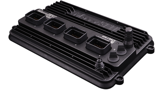
Model identification and capabilities
GEN2 RACE has 24 analogue and eight VR/Hall pulse inputs, eight type-K EGT inputs, dual wideband and dual knock. Its 550 kPa absolute MAP sensor, dual CAN, Wi-Fi, Bluetooth, USB-C and IP68-rated enclosure are identified on the manufacturer’s product page. Wideband support includes LSU 5.2, 4.9 and 4.2. Manufacturer specification; MaxxECU model comparison.
| Sequential cylinders, maximum | 12 |
|---|---|
| Injector outputs | 16 peak-and-hold |
| Ignition outputs | 12 selectable ignition/GP |
| Configuration | MTune; check the release appropriate to the ECU and hardware revision |
Identification and installation
GEN2 RACE has MX1 through MX4 connectors. MX3 differs from GEN2 TRACK; MX2 and MX4 are model-specific in the manufacturer’s reference. Check diagram version and hardware revision.
Record the model label, serial number, hardware revision, firmware, connector keying and loom. Outputs can be assigned or share functions; supported functions also depend on available I/O and software configuration. The figure in the comparison is a controller capability, not proof of compatibility with a particular engine or vehicle.
Connector and pinout
GEN2 RACE MX1 only. Use the manufacturer’s connector drawing for orientation and the remaining MX2–MX4 tables. These positions are manufacturer-labelled ECU functions, not an assurance that a particular loom or calibration uses them. Exact wiring and connector reference.
| Pin | Function |
|---|---|
| 1–4 | Ignition 1–4 respectively |
| 5–8 | GP outputs 1–4 (ground) respectively |
| 9 | Engine ground |
| 10 | Digital/VR 1 signal + |
| 11 | Digital/VR 1 signal − |
| 12 | Digital/VR 1 power supply |
| 13 | Digital/VR 1 shield |
| 14 | Sensor ground |
| 15 | CAN L |
| 16 | CAN H |
| 17 | GP output 5 (ground) |
| 18 | Digital/VR 2 signal + |
| 19 | Digital/VR 2 signal − |
| 20 | Digital/VR 2 power supply |
| 21 | Digital/VR 2 shield |
| 22 | 5 V supply |
| 23 | Digital/VR 3 signal + |
| 24 | Digital/VR 4 signal + |
| 25 | 12 V supply 1, main ECU supply |
| 26–30 | Analogue inputs 1–5 respectively |
| 31–34 | Injectors 1–4 respectively |
Consult the full diagram for wiring, grounds, supply fuses, driver limits, connector orientation and remaining positions. Sensor grounds and power grounds have different purposes; follow the matching manual.
Software and further documents
- MaxxECU GEN2 RACE: product information
- Model wiring and pinout reference
- MTune, quick-start guides and revision-specific wiring downloads
- MaxxECU family overview
Sources reviewed 17 November 2026.