Removed text is struck through; added text is highlighted.
MaxxECU SPORT — Six-cylinder sequential wire-in ECU with peak-and-hold injection and electronic-throttle outputs. MaxxECU product information.
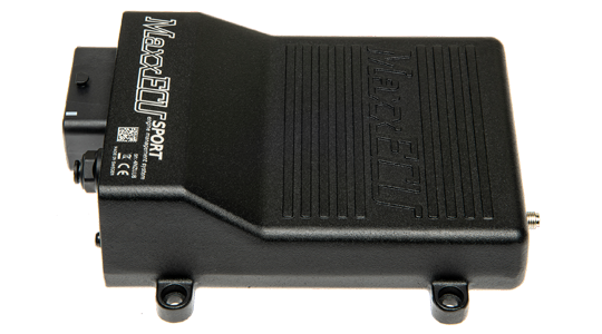
MaxxECU SPORT, manufacturer product image: MaxxECU. Used with permission.
Model identification and capabilities
SPORT has six peak-and-hold injector outputs, six ignition outputs, seven general ground outputs and two motor outputs. Inputs include two trigger inputs, two extra temperatures, six extra 0–5 V inputs, two digital inputs, an internal 400 kPa MAP sensor and a wideband controller for LSU 4.2/4.9. Its product page describes Bluetooth for MDash and USB for MTune. Manufacturer specification; MaxxECU model comparison.
Sequential cylinders, maximum6Injector outputs6 peak-and-holdIgnition outputs6ConfigurationMTune; check the release appropriate to the ECU and hardware revision
ProcessorThe manufacturer product page lists an ARM Cortex-M3 main processor running at 120 MHz (manufacturer specification). The specific microcontroller part number is not published.
Identification and installation
SPORT has different assignments from STREET and V1 on several positions of connector 1. Verify both connector columns and ECU revision; 5 V ignition signals require a suitable igniter or smart coil.
Record the model label, serial number, hardware revision, firmware, connector keying and loom. Outputs can be assigned or share functions; supported functions also depend on available I/O and software configuration. The figure in the comparison is a controller capability, not proof of compatibility with a particular engine or vehicle.
Connector and pinout
Complete 48-way connector 1 positions from the manufacturer’s model-specific column. A dash in the source is shown as not assigned. Consult the drawing for orientation and the remaining connectors. Exact wiring and connector reference.PositionManufacturer functionNotesA1GPO 4A2IGN 1A3IGN 2A4GPO 8/TACHO660ohm pullupB1GPO 5B2IGN 3B3IGN 4B4GPO 1C1AIN 5 (0-5V)C2IGN 5C3IGN 6C4GPO 2D1WBO2 Heater-D2AIN 6 (0-5V)D3AIN 7 (0-5V)D4GPO 3E1CAN HE2CAN LE3GND ShieldE4AIN 8 (0-5V)F1CLTF2IATF3WBO2 VREFF4WBO2 VSG1+5V sensor supply(peak 0.5A, max 150mA)G2TPS/AING3WBO2 IPG4WBO2 RCALH1Sensor GNDH2Trigger GNDH3TRIGGERH4HOMEJ1AIN 1 (temperature)J2AIN 2 (Temperature)J3AIN 3 (0-5V)J4AIN 4 (0-5V)K1INJ 1K2INJ 2K3DIN 1K4DIN 2L1GPO 11/Motor 1-L2GPO 12/MOTOR 1+L3INJ 6L4Engine GNDM1INJ 3M2INJ 4M3INJ 5M4+12V ECU power supplySelected 48-way connector 1 positions; these are shared in the manufacturer’s comparison. Consult the SPORT column for all positions and the physical view. These positions are manufacturer-labelled ECU functions, not an assurance that a particular loom or calibration uses them. Exact wiring and connector reference.PositionFunctionA2Ignition 1A3Ignition 2A4GPO 8 / tachoB2Ignition 3B3Ignition 4B4GPO 1C2Ignition 5C3Ignition 6C4GPO 2D1Wideband heater negativeD4GPO 3E1CAN highE2CAN lowE3Shield groundF1Coolant temperatureF2Air temperatureF3Wideband VREFF4Wideband VS
Consult the full diagram for wiring, grounds, supply fuses, driver limits, connector orientation and remaining positions. Sensor grounds and power grounds have different purposes; follow the matching manual.
All positions of the GEN1 connectors, including this unit's, are listed as a structured pin index in MaxxECU GEN1 connector pinout.
Software and further documents
MaxxECU SPORT: product informationModel wiring and pinout referenceMTune, quick-start guides and revision-specific wiring downloadsMaxxECU family overview
Sources reviewed 17 November 2026.
Rendered revisions
Open each version to inspect formatting, tables and photographs.
Revision 1: MaxxECU SPORT
MaxxECU SPORT — Six-cylinder sequential wire-in ECU with peak-and-hold injection and electronic-throttle outputs. MaxxECU product information.
MaxxECU SPORT, manufacturer product image: MaxxECU. Used with permission.
Model identification and capabilities
SPORT has six peak-and-hold injector outputs, six ignition outputs, seven general ground outputs and two motor outputs. Inputs include two trigger inputs, two extra temperatures, six extra 0–5 V inputs, two digital inputs, an internal 400 kPa MAP sensor and a wideband controller for LSU 4.2/4.9. Its product page describes Bluetooth for MDash and USB for MTune. Manufacturer specification; MaxxECU model comparison.
Sequential cylinders, maximum
6
Injector outputs
6 peak-and-hold
Ignition outputs
6
Configuration
MTune; check the release appropriate to the ECU and hardware revision
Identification and installation
SPORT has different assignments from STREET and V1 on several positions of connector 1. Verify both connector columns and ECU revision; 5 V ignition signals require a suitable igniter or smart coil.
Record the model label, serial number, hardware revision, firmware, connector keying and loom. Outputs can be assigned or share functions; supported functions also depend on available I/O and software configuration. The figure in the comparison is a controller capability, not proof of compatibility with a particular engine or vehicle.
Connector and pinout
Selected 48-way connector 1 positions; these are shared in the manufacturer’s comparison. Consult the SPORT column for all positions and the physical view. These positions are manufacturer-labelled ECU functions, not an assurance that a particular loom or calibration uses them. Exact wiring and connector reference.
Position
Function
A2
Ignition 1
A3
Ignition 2
A4
GPO 8 / tacho
B2
Ignition 3
B3
Ignition 4
B4
GPO 1
C2
Ignition 5
C3
Ignition 6
C4
GPO 2
D1
Wideband heater negative
D4
GPO 3
E1
CAN high
E2
CAN low
E3
Shield ground
F1
Coolant temperature
F2
Air temperature
F3
Wideband VREF
F4
Wideband VS
Consult the full diagram for wiring, grounds, supply fuses, driver limits, connector orientation and remaining positions. Sensor grounds and power grounds have different purposes; follow the matching manual.
MaxxECU SPORT — Six-cylinder sequential wire-in ECU with peak-and-hold injection and electronic-throttle outputs. MaxxECU product information.
MaxxECU SPORT, manufacturer product image: MaxxECU. Used with permission.
Model identification and capabilities
SPORT has six peak-and-hold injector outputs, six ignition outputs, seven general ground outputs and two motor outputs. Inputs include two trigger inputs, two extra temperatures, six extra 0–5 V inputs, two digital inputs, an internal 400 kPa MAP sensor and a wideband controller for LSU 4.2/4.9. Its product page describes Bluetooth for MDash and USB for MTune. Manufacturer specification; MaxxECU model comparison.
Sequential cylinders, maximum
6
Injector outputs
6 peak-and-hold
Ignition outputs
6
Configuration
MTune; check the release appropriate to the ECU and hardware revision
Processor
The manufacturer product page lists an ARM Cortex-M3 main processor running at 120 MHz (manufacturer specification). The specific microcontroller part number is not published.
Identification and installation
SPORT has different assignments from STREET and V1 on several positions of connector 1. Verify both connector columns and ECU revision; 5 V ignition signals require a suitable igniter or smart coil.
Record the model label, serial number, hardware revision, firmware, connector keying and loom. Outputs can be assigned or share functions; supported functions also depend on available I/O and software configuration. The figure in the comparison is a controller capability, not proof of compatibility with a particular engine or vehicle.
Connector and pinout
Complete 48-way connector 1 positions from the manufacturer’s model-specific column. A dash in the source is shown as not assigned. Consult the drawing for orientation and the remaining connectors. Exact wiring and connector reference.
Position
Manufacturer function
Notes
A1
GPO 4
A2
IGN 1
A3
IGN 2
A4
GPO 8/TACHO
660ohm pullup
B1
GPO 5
B2
IGN 3
B3
IGN 4
B4
GPO 1
C1
AIN 5 (0-5V)
C2
IGN 5
C3
IGN 6
C4
GPO 2
D1
WBO2 Heater-
D2
AIN 6 (0-5V)
D3
AIN 7 (0-5V)
D4
GPO 3
E1
CAN H
E2
CAN L
E3
GND Shield
E4
AIN 8 (0-5V)
F1
CLT
F2
IAT
F3
WBO2 VREF
F4
WBO2 VS
G1
+5V sensor supply
(peak 0.5A, max 150mA)
G2
TPS/AIN
G3
WBO2 IP
G4
WBO2 RCAL
H1
Sensor GND
H2
Trigger GND
H3
TRIGGER
H4
HOME
J1
AIN 1 (temperature)
J2
AIN 2 (Temperature)
J3
AIN 3 (0-5V)
J4
AIN 4 (0-5V)
K1
INJ 1
K2
INJ 2
K3
DIN 1
K4
DIN 2
L1
GPO 11/Motor 1-
L2
GPO 12/MOTOR 1+
L3
INJ 6
L4
Engine GND
M1
INJ 3
M2
INJ 4
M3
INJ 5
M4
+12V ECU power supply
Consult the full diagram for wiring, grounds, supply fuses, driver limits, connector orientation and remaining positions. Sensor grounds and power grounds have different purposes; follow the matching manual.
All positions of the GEN1 connectors, including this unit's, are listed as a structured pin index in MaxxECU GEN1 connector pinout.