Individual model references
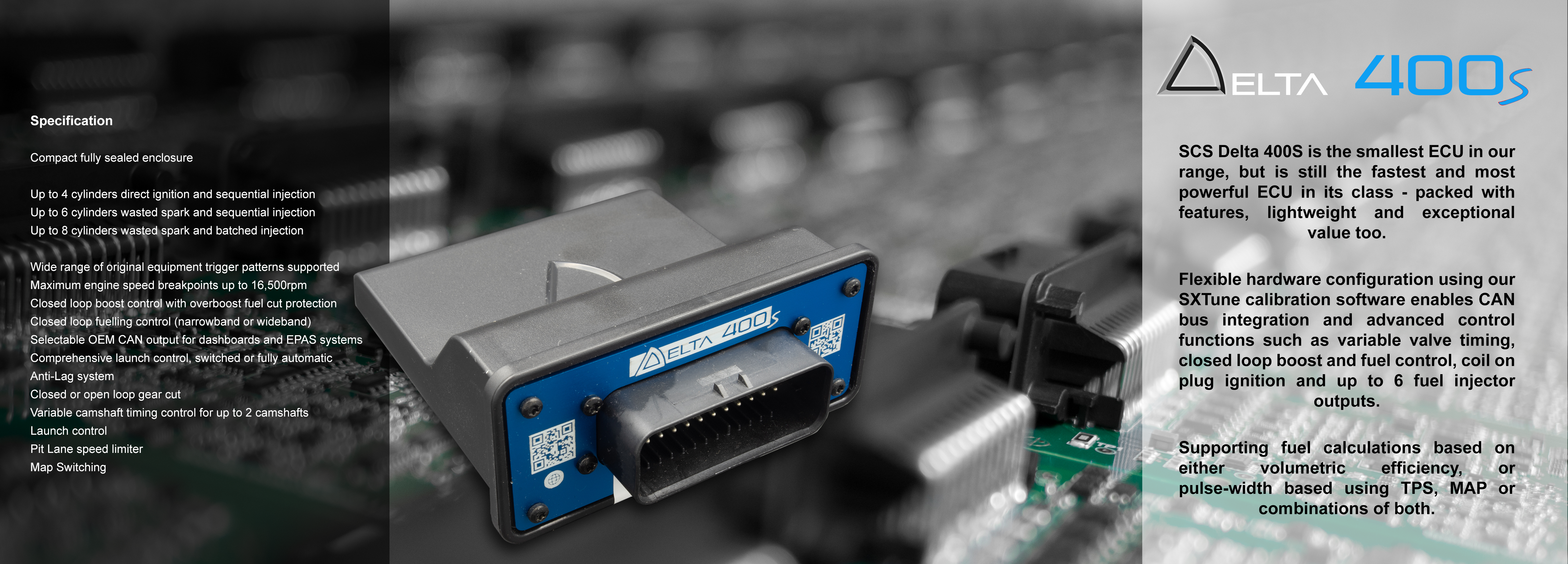
Specialist Control Systems produces the SCS Delta programmable ECU range. Hardware configuration, connector pinout and firmware must be matched to the exact unit. SXTune ECU technical reference and product photographs
ECU families
- Delta 400, 700 and 900: models with manufacturer connector documentation.
- Delta GDI6: direct-injection model with its own three-connector pinout.
- Delta 800, 880 and GDI4: earlier Delta units in the manufacturer wiring reference.
- Earlier SC systems: Typhoon, Typhoon 2, Storm, Storm 2, Tornado, Tornado 2, Tornado GDI and Hurricane. SCS identifies specified 2008–2015 units as unsupported; the precise model and replacement wiring requirements matter. SCS discontinued models · SCS base maps
- SDI4: diesel ECU identified in AiM's SCS ECU communications reference.
This list records documented families and is not an exhaustive list of special editions or application-specific units.
Delta 400 connector A pinout
For Delta 400 only, connector A AMPSeal 776164-1. Refer to the manufacturer's Delta 400 pinout for diagram, terminals, current limits, fuse values and connection orientation. Functions shown include the manufacturer's typical assignments; configurable inputs and outputs depend on calibration.
| Pin | Function |
|---|---|
| A1 | Battery supply |
| A2 | Ignition switched supply |
| A3 | Power ground 1 |
| A4 | Low side output 1 / injector 1 |
| A5 | Low side output 2 / injector 2 |
| A6 | Low side output 3 / injector 3 |
| A7 | Low side output 4 / injector 4 |
| A8 | Crank/cam sensor ground |
| A9 | Crank sensor |
| A10 | Cam sensor 1 |
| A11 | Coolant temperature |
| A12 | Air temperature |
| A13 | Ignition 1 |
| A14 | Ignition 2 |
| A15 | Ignition 3 |
| A16 | Ignition 4 |
| A17 | Analogue input 1 |
| A18 | Cam 2 / wheel speed |
| A19 | Analogue ground 1 |
| A20 | Lambda 1 input |
| A21 | CAN 1 high |
| A22 | CAN 1 low |
| A23 | Low side output 5 / multifunction I/O |
| A24 | Low side output 7 / main relay, PWM 1 |
| A25 | Low side output 8 / fuel pump relay, PWM 2 |
| A26 | Low side output 9 / PWM 3 |
| A27 | Low side output 10 / PWM 4 |
| A28 | Low side output 11 / tacho |
| A29 | Low side output 6 / multifunction I/O |
| A30 | Analogue ground 2 |
| A31 | NTC input 3 |
| A32 | Analogue input 2 / TPS 1 |
| A33 | Analogue input 3 / MAP |
| A34 | 5 V sensor reference |
| A35 | Power ground 2 |