Removed text is struck through; added text is highlighted.
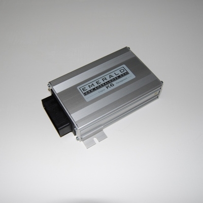
Emerald K6+ is an Emerald engine-management designation. Six injection and six ignition drivers; three speed triggers; TPS and/or MAP load; CAN 2.0B; triple map switching. The generic unit is supplied with starting maps and configurations that still require engine-specific setup. Emerald manufacturer information.
K6+ product image: Emerald M3D; permission to republish confirmed by the user.
Identification and configuration
Identify the exact hardware and serial number. Emerald notes that some units have bespoke software for non-standard installations, and that many M3DK units were upgraded to K3 specification. An old case label alone cannot establish the internal specification. Emerald earlier ECU information; software and manuals.
Emerald provides a K3/K6 software family separately from M3DK software. Its K6 generic and preconfigured packages are ordering/configuration choices; a base map is a starting point requiring matching and calibration for the actual engine.
Pinout, harness and software
Use the K6/K6+ documentation and the actual configuration in the manufacturer's manuals index. A DBW part-loom wiring diagram applies only to its stated configuration. Manufacturer manual or documentation. Use terminal markings, exact connector view and the source's wiring and driver notes. A model-specific adapter for an original vehicle harness is distinct from the generic connector assignment.
See Emerald adapter catalogue and Emerald standalone ECU overview.
36-way manufacturer DBW part-loom exampleEmerald’s K6 part-loom schedule for drive-by-wire with inductive crank and cam sensors identifies every connector cavity, viewed from the cable-entry side. This is a specific DBW loom configuration, not an assurance that every K6/K6+ hardware revision or loom uses identical assignments. Match the ECU configuration and serial number with Emerald. The manufacturer sheet includes an older hardware-v1.40 example; verify its applicability before wiring a particular unit.PinExample wire colourDocumented function1Yellow/blackInjector driver 4 / AuxOut12Orange/blueIACV2; DBW motor (+)3Orange/greenIACV1; DBW motor (−)4Green/yellowIgnition driver 3 or main relay5Green/blackIgnition driver 2 / AuxOut56Blue/yellowCooling fan relay7White/pinkThrottle position signal B8GreenThrottle position signal A9Red+5 V sensor supply (100 mA maximum)10White/yellowAuxIn10; configurable internal pull-up11Red/blackIgnition sense input (+12 V switched)12YellowTacho output13White/greenImmobiliser / auxiliary digital input14Blue/redAuxIn14 / AuxOut1415RedCam sync signal16WhiteAir temperature signal17Yellow/pinkInjector driver 5 / AuxOut1718White/blackOxygen sensor signal earth19Blue/whiteIgnition driver 4 / shift-light driver20BrownFuel pump relay driver21Yellow/orangeInjector driver 6 / AuxOut2122Orange/pinkIACV3 / AuxOut2223Yellow/redInjector driver 224Yellow/brownInjector driver 125Green/whiteIgnition driver 126Yellow/whiteInjector driver 3 / AuxOut2627Orange/slateIACV4 / AuxOut2728Red+12 V supply from main relay or common with pin 1129BlackECU ground30BlackSensor ground31RedMain crank trigger signal32BlackCrank/cam trigger sensor ground33BlueCoolant temperature signal34PurpleAuxIn34, commonly MAP35White/redAuxIn35 / DBW pedal position A36Blue/blackAuxIn36 / AuxOut36 / DBW pedal position BFunctions separated by slashes depend on configuration. Emerald specifies that pin 30 is for sensor return and must not be connected to battery or chassis ground. Consult the manufacturer drawing for crank and cam shielding and configure ignition drivers before connecting coils.Structured connector pinoutThe 36-way connector above is given as a structured pin index with a redrawn connector face (view from cable entry) in Emerald K6 and K6+ 36-way connector pinout. Emerald's published K6 documentation does not name the ECU's microcontroller.
Rendered revisions
Open each version to inspect formatting, tables and photographs.
Revision 1: Emerald K6+
Emerald K6+ is an Emerald engine-management designation. Six injection and six ignition drivers; three speed triggers; TPS and/or MAP load; CAN 2.0B; triple map switching. The generic unit is supplied with starting maps and configurations that still require engine-specific setup. Emerald manufacturer information.
K6+ product image: Emerald M3D; permission to republish confirmed by the user.
Identification and configuration
Identify the exact hardware and serial number. Emerald notes that some units have bespoke software for non-standard installations, and that many M3DK units were upgraded to K3 specification. An old case label alone cannot establish the internal specification. Emerald earlier ECU information; software and manuals.
Emerald provides a K3/K6 software family separately from M3DK software. Its K6 generic and preconfigured packages are ordering/configuration choices; a base map is a starting point requiring matching and calibration for the actual engine.
Pinout, harness and software
Use the K6/K6+ documentation and the actual configuration in the manufacturer's manuals index. A DBW part-loom wiring diagram applies only to its stated configuration. Manufacturer manual or documentation. Use terminal markings, exact connector view and the source's wiring and driver notes. A model-specific adapter for an original vehicle harness is distinct from the generic connector assignment.
Emerald K6+ is an Emerald engine-management designation. Six injection and six ignition drivers; three speed triggers; TPS and/or MAP load; CAN 2.0B; triple map switching. The generic unit is supplied with starting maps and configurations that still require engine-specific setup. Emerald manufacturer information.
K6+ product image: Emerald M3D; permission to republish confirmed by the user.
Identification and configuration
Identify the exact hardware and serial number. Emerald notes that some units have bespoke software for non-standard installations, and that many M3DK units were upgraded to K3 specification. An old case label alone cannot establish the internal specification. Emerald earlier ECU information; software and manuals.
Emerald provides a K3/K6 software family separately from M3DK software. Its K6 generic and preconfigured packages are ordering/configuration choices; a base map is a starting point requiring matching and calibration for the actual engine.
Pinout, harness and software
Use the K6/K6+ documentation and the actual configuration in the manufacturer's manuals index. A DBW part-loom wiring diagram applies only to its stated configuration. Manufacturer manual or documentation. Use terminal markings, exact connector view and the source's wiring and driver notes. A model-specific adapter for an original vehicle harness is distinct from the generic connector assignment.
Emerald’s K6 part-loom schedule for drive-by-wire with inductive crank and cam sensors identifies every connector cavity, viewed from the cable-entry side. This is a specific DBW loom configuration, not an assurance that every K6/K6+ hardware revision or loom uses identical assignments. Match the ECU configuration and serial number with Emerald. The manufacturer sheet includes an older hardware-v1.40 example; verify its applicability before wiring a particular unit.
Pin
Example wire colour
Documented function
1
Yellow/black
Injector driver 4 / AuxOut1
2
Orange/blue
IACV2; DBW motor (+)
3
Orange/green
IACV1; DBW motor (−)
4
Green/yellow
Ignition driver 3 or main relay
5
Green/black
Ignition driver 2 / AuxOut5
6
Blue/yellow
Cooling fan relay
7
White/pink
Throttle position signal B
8
Green
Throttle position signal A
9
Red
+5 V sensor supply (100 mA maximum)
10
White/yellow
AuxIn10; configurable internal pull-up
11
Red/black
Ignition sense input (+12 V switched)
12
Yellow
Tacho output
13
White/green
Immobiliser / auxiliary digital input
14
Blue/red
AuxIn14 / AuxOut14
15
Red
Cam sync signal
16
White
Air temperature signal
17
Yellow/pink
Injector driver 5 / AuxOut17
18
White/black
Oxygen sensor signal earth
19
Blue/white
Ignition driver 4 / shift-light driver
20
Brown
Fuel pump relay driver
21
Yellow/orange
Injector driver 6 / AuxOut21
22
Orange/pink
IACV3 / AuxOut22
23
Yellow/red
Injector driver 2
24
Yellow/brown
Injector driver 1
25
Green/white
Ignition driver 1
26
Yellow/white
Injector driver 3 / AuxOut26
27
Orange/slate
IACV4 / AuxOut27
28
Red
+12 V supply from main relay or common with pin 11
29
Black
ECU ground
30
Black
Sensor ground
31
Red
Main crank trigger signal
32
Black
Crank/cam trigger sensor ground
33
Blue
Coolant temperature signal
34
Purple
AuxIn34, commonly MAP
35
White/red
AuxIn35 / DBW pedal position A
36
Blue/black
AuxIn36 / AuxOut36 / DBW pedal position B
Functions separated by slashes depend on configuration. Emerald specifies that pin 30 is for sensor return and must not be connected to battery or chassis ground. Consult the manufacturer drawing for crank and cam shielding and configure ignition drivers before connecting coils.
Structured connector pinout
The 36-way connector above is given as a structured pin index with a redrawn connector face (view from cable entry) in Emerald K6 and K6+ 36-way connector pinout. Emerald's published K6 documentation does not name the ECU's microcontroller.