Removed text is struck through; added text is highlighted.
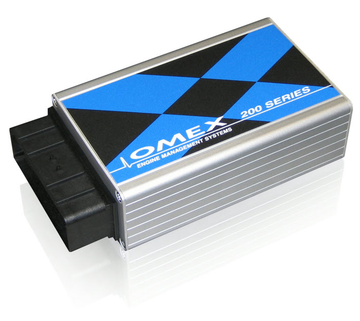
Omex 200 Series manufacturer photograph from the Omex 200 installation manual release 2v00, cover, hosted by Northampton Motorsport; reproduced with permission.
The 200 is an ignition-only ECU rather than a full fuel-injection controller. Its installation manual identifies two amplified ignition outputs for single-coil/distributor or wasted-spark configurations. It describes inputs for crank position, throttle, temperature and MAP, as well as relay-controlled fuel pump and fan functions. Individual hardware modifications may be necessary for particular coil-on-plug arrangements. Model-specific Omex manual · Omex engine-management range.
Connector and pinout
The exact loom-side connector table and diagrams are in section 4.3 of Omex installation manual 2v10. The guide identifies FTG input at 10A; do not transfer the 600 pinout to a 200. Open the exact-model installation or hardware manual.
Software and setup
Omex lists MAP4000 for its current ECU range; check the exact unit, firmware and communications lead before attempting to connect. Record ECU serial and firmware, save the existing calibration, and confirm crank trigger, injector, coil, sensors and assigned outputs against the matching manual. Manufacturer startup calibrations require verification and adjustment for the actual engine.
Compare models and historical identities in the Omex family guide.
Omex 200 main connector pinoutFrom the Omex OMEM200 installation manual 2v10, pages 22–23. Connector orientation is from the wiring-loom side, with rows A to C and positions 1 to 12. Blank cells in the manufacturer table are shown as “not specified”; they must not be assumed electrically unused. Two-colour wire main and tracer colours may be reversed. Confirm the specific loom and ECU configuration.PinWire colourFunction1AVioletIgnition 12ANot specifiedNot specified3ANot specifiedNot specified4ARedBattery power5ABlackChassis earth 16AGreySensor ground7ABlack screened redCrank sensor8ABlue screened-cable conductorsTiming ground9AWhite/violetCoolant temperature sensor10AWhite/yellowFull-throttle gearshift input11ANot specifiedNot specified12AYellowIgnition 21BNot specifiedNot specified2BNot specifiedNot specified3BNot specifiedNot specified4BNot specifiedNot specified5BBlue/whiteFuel pump6BGreenMAP sensor7BBlackChassis earth 28BBlue/greyShift light9BGreen/whiteAir temperature sensor10BNot specifiedNot specified11BWhite/orangeAlt mode input12BYellow/redRadiator fan 2 (bay fan)1CNot specifiedNot specified2CNot specifiedNot specified3CNot specifiedNot specified4CYellow/blackVTEC5CNot specifiedNot specified6CBlue/blackRadiator fan7CNot specifiedNot specified8COrangeThrottle position sensor9CPink5 V out10CNot specifiedNot specified11CNot specifiedNot specified12CBlue/yellowTachoThe manual's table calls 4A battery power, while its typical-wiring diagram labels the red supply ignition 12 V; resolve the intended supply for the specific installation with Omex before wiring. The source identifies 10A as a switch-to-earth full-throttle gearshift input, and 11B as a +12 V alt-mode input. Refer to the complete manual for the exact sensor, relay and coil wiring.
Rendered revisions
Open each version to inspect formatting, tables and photographs.
Revision 1: Omex 200
The 200 is an ignition-only ECU rather than a full fuel-injection controller. Its installation manual identifies two amplified ignition outputs for single-coil/distributor or wasted-spark configurations. It describes inputs for crank position, throttle, temperature and MAP, as well as relay-controlled fuel pump and fan functions. Individual hardware modifications may be necessary for particular coil-on-plug arrangements. Model-specific Omex manual · Omex engine-management range.
Connector and pinout
The exact loom-side connector table and diagrams are in section 4.3 of Omex installation manual 2v10. The guide identifies FTG input at 10A; do not transfer the 600 pinout to a 200. Open the exact-model installation or hardware manual.
Software and setup
Omex lists MAP4000 for its current ECU range; check the exact unit, firmware and communications lead before attempting to connect. Record ECU serial and firmware, save the existing calibration, and confirm crank trigger, injector, coil, sensors and assigned outputs against the matching manual. Manufacturer startup calibrations require verification and adjustment for the actual engine.
Revision 4: Omex 200Omex 200 Series manufacturer photograph from the Omex 200 installation manual release 2v00, cover, hosted by Northampton Motorsport; reproduced with permission.
The 200 is an ignition-only ECU rather than a full fuel-injection controller. Its installation manual identifies two amplified ignition outputs for single-coil/distributor or wasted-spark configurations. It describes inputs for crank position, throttle, temperature and MAP, as well as relay-controlled fuel pump and fan functions. Individual hardware modifications may be necessary for particular coil-on-plug arrangements. Model-specific Omex manual · Omex engine-management range.
Connector and pinout
The exact loom-side connector table and diagrams are in section 4.3 of Omex installation manual 2v10. The guide identifies FTG input at 10A; do not transfer the 600 pinout to a 200. Open the exact-model installation or hardware manual.
Software and setup
Omex lists MAP4000 for its current ECU range; check the exact unit, firmware and communications lead before attempting to connect. Record ECU serial and firmware, save the existing calibration, and confirm crank trigger, injector, coil, sensors and assigned outputs against the matching manual. Manufacturer startup calibrations require verification and adjustment for the actual engine.
From the Omex OMEM200 installation manual 2v10, pages 22–23. Connector orientation is from the wiring-loom side, with rows A to C and positions 1 to 12. Blank cells in the manufacturer table are shown as “not specified”; they must not be assumed electrically unused. Two-colour wire main and tracer colours may be reversed. Confirm the specific loom and ECU configuration.
Pin
Wire colour
Function
1A
Violet
Ignition 1
2A
Not specified
Not specified
3A
Not specified
Not specified
4A
Red
Battery power
5A
Black
Chassis earth 1
6A
Grey
Sensor ground
7A
Black screened red
Crank sensor
8A
Blue screened-cable conductors
Timing ground
9A
White/violet
Coolant temperature sensor
10A
White/yellow
Full-throttle gearshift input
11A
Not specified
Not specified
12A
Yellow
Ignition 2
1B
Not specified
Not specified
2B
Not specified
Not specified
3B
Not specified
Not specified
4B
Not specified
Not specified
5B
Blue/white
Fuel pump
6B
Green
MAP sensor
7B
Black
Chassis earth 2
8B
Blue/grey
Shift light
9B
Green/white
Air temperature sensor
10B
Not specified
Not specified
11B
White/orange
Alt mode input
12B
Yellow/red
Radiator fan 2 (bay fan)
1C
Not specified
Not specified
2C
Not specified
Not specified
3C
Not specified
Not specified
4C
Yellow/black
VTEC
5C
Not specified
Not specified
6C
Blue/black
Radiator fan
7C
Not specified
Not specified
8C
Orange
Throttle position sensor
9C
Pink
5 V out
10C
Not specified
Not specified
11C
Not specified
Not specified
12C
Blue/yellow
Tacho
The manual's table calls 4A battery power, while its typical-wiring diagram labels the red supply ignition 12 V; resolve the intended supply for the specific installation with Omex before wiring. The source identifies 10A as a switch-to-earth full-throttle gearshift input, and 11B as a +12 V alt-mode input. Refer to the complete manual for the exact sensor, relay and coil wiring.