Removed text is struck through; added text is highlighted.
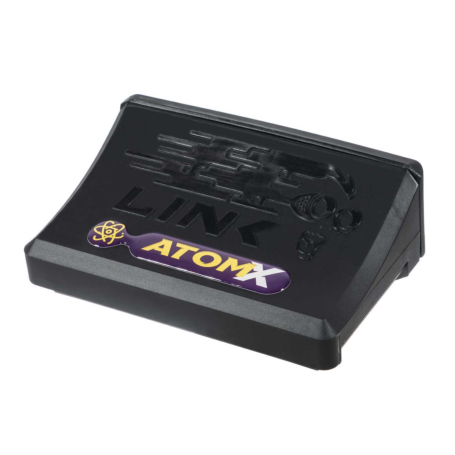
G4X AtomX manufacturer photograph: Link ECU. Permission to republish confirmed by the user.
Link G4X AtomX is a programmable G4X wire-in engine-management ECU. One A loom. The documented V3 and newer hardware supports knock through pin 6; earlier hardware lacks that knock circuit. Link G4X AtomX quick-start guide.
Model identification and I/O
ItemDocumented detailsECU familyG4XOutputs4 injection and 4 ignition drivesProgrammingPCLink version matched to ECU generation and firmwareConnector and loomSee the exact-model guide, including connector keys, wire-side orientation and optional functions
The manufacturer guidance and wiring identify the hardware; driver counts do not establish injector electrical compatibility or imply all multiplexed pins can be used at the same time.
Model-specific pinout and installation
The G4X AtomX quick-start guide provides the connector diagrams and installer I/O table. Refer to that version for numbered cavities, wire colours, supply, grounds, driver and sensor connection notes. Loom wire-side and ECU header views are identified on the diagram; do not transfer a pin number from another generation.
Complete loom connector tablesThe following positions are transcribed from the Link ATOMX quick-start guide. They are viewed into the ECU header or the wire side of the loom, as illustrated in the source. Unlabelled positions are shown as such, rather than assumed unused. Colours apply to the documented loom; outputs and shared functions depend on ECU hardware version and configuration. Refer to the original for keying, current limits and full installation diagrams.A/B loom connector A — 34-wayPinFunction in guideLoom colour1Injector 4Brown/Orange2Injector 3Brown/Red3Injector 2Brown4Injector 1Brown/Black5+14 VRed6Knock, hardware version 3 or newerRed/White7Shield/GroundGreen8Trigger 1Black9Trigger 2Red10Ignition 4Blue/Orange11Ignition 3Blue/Red12Ignition 2Blue/Brown13Ignition 1Blue14Not labelled in guide—15Temperature 1Yellow16Temperature 2Yellow/Brown17Analogue voltage 1Yellow/Blue18Auxiliary 4Orange19Auxiliary 3Orange/Red20Auxiliary 2Orange/Brown21Auxiliary 1Orange/Black22Analogue voltage 2White/Brown23Not labelled in guide—24Ground outGreen25GroundBlack26Not labelled in guide—27Not labelled in guide—28CAN highOrange/Green29CAN lowOrange/Yellow30Digital input 1Grey/Black31Digital input 2Grey/Brown32+5 VRed/Blue33Analogue voltage 3Yellow/Black34GroundBlack
Software and further sources
Download software, firmware and full installation help from Link's download centre; identify the ECU generation and installed firmware before choosing a PCLink package. The legacy software list separates G5, G4X and G4+ compatibility. See also Link standalone ECUs.
Rendered revisions
Open each version to inspect formatting, tables and photographs.
Revision 1: Link G4X AtomX
Link G4X AtomX is a programmable G4X wire-in engine-management ECU. One A loom. The documented V3 and newer hardware supports knock through pin 6; earlier hardware lacks that knock circuit. Link G4X AtomX quick-start guide.
Model identification and I/O
Item
Documented details
ECU family
G4X
Outputs
4 injection and 4 ignition drives
Programming
PCLink version matched to ECU generation and firmware
Connector and loom
See the exact-model guide, including connector keys, wire-side orientation and optional functions
The manufacturer guidance and wiring identify the hardware; driver counts do not establish injector electrical compatibility or imply all multiplexed pins can be used at the same time.
Model-specific pinout and installation
The G4X AtomX quick-start guide provides the connector diagrams and installer I/O table. Refer to that version for numbered cavities, wire colours, supply, grounds, driver and sensor connection notes. Loom wire-side and ECU header views are identified on the diagram; do not transfer a pin number from another generation.
Software and further sources
Download software, firmware and full installation help from Link's download centre; identify the ECU generation and installed firmware before choosing a PCLink package. The legacy software list separates G5, G4X and G4+ compatibility. See also Link standalone ECUs.
Revision 3: Link G4X AtomXG4X AtomX manufacturer photograph: Link ECU. Permission to republish confirmed by the user.
Link G4X AtomX is a programmable G4X wire-in engine-management ECU. One A loom. The documented V3 and newer hardware supports knock through pin 6; earlier hardware lacks that knock circuit. Link G4X AtomX quick-start guide.
Model identification and I/O
Item
Documented details
ECU family
G4X
Outputs
4 injection and 4 ignition drives
Programming
PCLink version matched to ECU generation and firmware
Connector and loom
See the exact-model guide, including connector keys, wire-side orientation and optional functions
The manufacturer guidance and wiring identify the hardware; driver counts do not establish injector electrical compatibility or imply all multiplexed pins can be used at the same time.
Model-specific pinout and installation
The G4X AtomX quick-start guide provides the connector diagrams and installer I/O table. Refer to that version for numbered cavities, wire colours, supply, grounds, driver and sensor connection notes. Loom wire-side and ECU header views are identified on the diagram; do not transfer a pin number from another generation.
Complete loom connector tables
The following positions are transcribed from the Link ATOMX quick-start guide. They are viewed into the ECU header or the wire side of the loom, as illustrated in the source. Unlabelled positions are shown as such, rather than assumed unused. Colours apply to the documented loom; outputs and shared functions depend on ECU hardware version and configuration. Refer to the original for keying, current limits and full installation diagrams.
A/B loom connector A — 34-way
Pin
Function in guide
Loom colour
1
Injector 4
Brown/Orange
2
Injector 3
Brown/Red
3
Injector 2
Brown
4
Injector 1
Brown/Black
5
+14 V
Red
6
Knock, hardware version 3 or newer
Red/White
7
Shield/Ground
Green
8
Trigger 1
Black
9
Trigger 2
Red
10
Ignition 4
Blue/Orange
11
Ignition 3
Blue/Red
12
Ignition 2
Blue/Brown
13
Ignition 1
Blue
14
Not labelled in guide
—
15
Temperature 1
Yellow
16
Temperature 2
Yellow/Brown
17
Analogue voltage 1
Yellow/Blue
18
Auxiliary 4
Orange
19
Auxiliary 3
Orange/Red
20
Auxiliary 2
Orange/Brown
21
Auxiliary 1
Orange/Black
22
Analogue voltage 2
White/Brown
23
Not labelled in guide
—
24
Ground out
Green
25
Ground
Black
26
Not labelled in guide
—
27
Not labelled in guide
—
28
CAN high
Orange/Green
29
CAN low
Orange/Yellow
30
Digital input 1
Grey/Black
31
Digital input 2
Grey/Brown
32
+5 V
Red/Blue
33
Analogue voltage 3
Yellow/Black
34
Ground
Black
Software and further sources
Download software, firmware and full installation help from Link's download centre; identify the ECU generation and installed firmware before choosing a PCLink package. The legacy software list separates G5, G4X and G4+ compatibility. See also Link standalone ECUs.