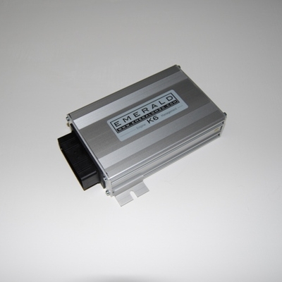
Emerald M3D supplies programmable standalone engine management, including generic and pre-configured ECUs. K6+ has six injector and six ignition drivers, configurable load sensing, map switching and CAN. Emerald K6+ product details.
Models and history
- K6 and K6+: K6-family programmable ECUs, with generic and pre-configured variants. K6+ specifications; manuals.
- K3: earlier ECU sharing a software and manual family with K6. Earlier ECUs.
- M3DK: 32-bit ECU made March 2001 to February 2007; some examples were upgraded to K3 specification. Identify actual hardware and serial, not only an old label. Emerald history.
- M3D: the earlier 16-bit generation preceding M3DK. Emerald history.
Emerald notes that individual units may have bespoke software for non-standard installations; quote the serial number when identifying the correct software. Software and manuals.
Example pinout: Emerald K3 main connector
36-way positions and generic functions from Emerald K3 manual v057, page 56. Use moulded cavity numbers and the manufacturer's connector drawing to establish viewing orientation; do not assume this is a K6, K6+ or bespoke ECU pinout.
| Pin | Function |
|---|---|
| 1 | Injector 4 / AuxOut1 |
| 2 | IACV2 / AuxOut2 |
| 3 | IACV1 / IACV PWM / AuxOut3 |
| 4 | Ignition 3 / main relay |
| 5 | Ignition 2 / AuxOut5 |
| 6 | Cooling fan relay |
| 7 | Narrowband oxygen signal, 0–1 V |
| 8 | Throttle position signal |
| 9 | +5 V sensor supply, 100 mA maximum |
| 10 | AuxIn10 |
| 11 | Ignition sense, switched +12 V |
| 12 | Tacho |
| 13 | Immobiliser / EGT digital input |
| 14 | +8 V sensor supply |
| 15 | Cam phase / custom input |
| 16 | Air temperature |
| 17 | Injector 5 / ignition 4 / AuxOut17 |
| 18 | Oxygen sensor signal earth |
| 19 | Shift light / AuxOut19 |
| 20 | Fuel pump relay |
| 21 | Injector 6 / configurable auxiliary output |
| 22 | IACV3 / AuxOut22 |
| 23 | Injector 2 |
| 24 | Injector 1 |
| 25 | Ignition 1 |
| 26 | Injector 3 / AuxOut26 |
| 27 | IACV4 / AuxOut27 |
| 28 | +12 V ignition supply |
| 29 | ECU earth |
| 30 | Sensor earth |
| 31 | Main trigger input |
| 32 | Main trigger sensor earth |
| 33 | Coolant temperature |
| 34 | AuxIn34 |
| 35 | AuxIn35 |
| 36 | AuxIn36 / AuxOut36 |
Slash-separated functions depend on configuration. The K3 manual describes driver outputs except tacho as switched earths, and specifies high-impedance injectors or appropriately sized ballast for low-impedance injectors. Confirm hardware and configuration before connecting coils and injectors.
Further documentation
- K3/K6 manual, K6 quick-start and configuration guides.
- K6 drive-by-wire part-loom pin table: a particular DBW configuration, not a universal K6 allocation. Pin 7 differs from the K3 table above.
- K3 and M3DK information.
Sources reviewed 17 November 2026.