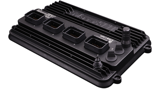
Product photograph: MaxxECU. Used with permission.
MaxxECU produces programmable standalone engine management systems configured with MTune. Product families include universal and vehicle-specific plug-in installations.
Models
- MINI, STREET, SPORT, RACE, RACE H2O and PRO.
- GEN2 TRACK and GEN2 RACE: newer generation.
- V1: earlier generation, still included in the manufacturer's GEN1 wiring reference.
The manufacturer’s comparison describes supported features; GEN2 RACE product page includes product photographs. Do not assume connectors or capabilities match across versions.
GEN2 RACE MX1 pinout
Connector 1 (MX1), GEN2 RACE only. Pin numbers are the manufacturer's numbers; consult its connector drawing for orientation. Engine ground goes to the cylinder head; sensor ground must not be connected to engine ground. Manufacturer's full GEN2 pinouts and limitations
| Pin | Function |
|---|---|
| 1–4 | Ignition 1–4 respectively |
| 5–8 | GP outputs 1–4 (ground) respectively |
| 9 | Engine ground |
| 10 | Digital/VR 1 signal + |
| 11 | Digital/VR 1 signal − |
| 12 | Digital/VR 1 power supply |
| 13 | Digital/VR 1 shield |
| 14 | Sensor ground |
| 15 | CAN L |
| 16 | CAN H |
| 17 | GP output 5 (ground) |
| 18 | Digital/VR 2 signal + |
| 19 | Digital/VR 2 signal − |
| 20 | Digital/VR 2 power supply |
| 21 | Digital/VR 2 shield |
| 22 | 5 V supply |
| 23 | Digital/VR 3 signal + |
| 24 | Digital/VR 4 signal + |
| 25 | 12 V supply 1, main ECU supply |
| 26–30 | Analogue inputs 1–5 respectively |
| 31–34 | Injectors 1–4 respectively |
For GEN2 RACE MX2, MX3, MX4 and GEN2 TRACK MX3, use the full linked table. The GEN1 connector tables cover STREET/SPORT/V1/RACE/PRO; pin functions differ. Revision-specific wiring downloads
Confirm the exact ECU, hardware revision and connector orientation before wiring. Configurable functions and electrical limits are model-dependent; consult the linked original diagrams.