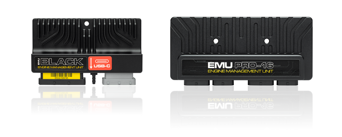
ECUMaster's standalone engine management families include EMU Classic, EMU Black, EMU Pro-8 and EMU Pro-16. The manufacturer provides a model comparison with product photographs and current downloads and application-specific pinouts.
Models
- EMU Classic: 48 pins across two FCI connectors; six high-impedance injector outputs. Drive-by-wire requires an external module.
- EMU Black: 63 pins across two FCI connectors; up to eight high-impedance injector outputs, including two shared auxiliary outputs; one drive-by-wire controller. There are also application-specific plug-in units.
- EMU Pro-8: 96 pins across three AMP Superseal connectors; eight peak-and-hold injector outputs.
- EMU Pro-16: 120 pins across four AMP Superseal connectors; 16 peak-and-hold injector outputs.
Pro-8 and Pro-16 direct-injection applications require a separate GDI driver. Figures are from the manufacturer comparison. Different plug-in models have vehicle-specific connections; do not apply the universal wire-in diagrams to them. DET3 is a piggyback controller and is outside this standalone list.
EMU Black pinout
Universal EMU Black wire-in ECU only. Connector colour and pin numbers follow ECUMaster's EMU Black pinout PDF; refer to the manufacturer's drawings for connector view and orientation, electrical limits, sensor wiring and setup. Shared outputs depend on calibration.
Black 39-pin connector
| Pin | Function |
|---|---|
| 1 | Ignition coil 5 |
| 2 | EGT input 1 |
| 3 | Knock sensor input 1 |
| 4 | Analogue input 2 |
| 5 | Coolant temperature input |
| 6 | Wideband oxygen Vs |
| 7 | Cam sync input 2 |
| 8 | Primary trigger |
| 9 | Flex fuel input |
| 10 | Switch input 1 |
| 11 | RS232 TXD |
| 12 | CAN high |
| 13 | Battery +12 V |
| 14 | Ignition coil 4 |
| 15 | EGT input 2 |
| 16 | Knock sensor input 2 |
| 17 | Analogue input 3 |
| 18 | Throttle position input |
| 19 | Wideband oxygen Ip |
| 20 | Vehicle speed input |
| 21 | Cam sync input 1 |
| 22 | Wideband oxygen Rcal |
| 23 | Switch input 2 |
| 24 | RS232 RXD |
| 25 | CAN low |
| 26 | 5 V supply |
| 27 | Power ground |
| 28 | ECU ground |
| 29 | Sensor ground |
| 30 | Analogue input 4 |
| 31 | Analogue input 1 |
| 32 | Intake air temperature input |
| 33 | Wideband oxygen VGND |
| 34 | 5 V supply |
| 35 | Analogue input 5 |
| 36 | Switch input 3 |
| 37 | Analogue input 6 |
| 38 | Sensor ground |
| 39 | Sensor ground |
Grey 24-pin connector
| Pin | Function |
|---|---|
| 1 | Ignition coil 6 |
| 2 | H-bridge 1 winding A |
| 3 | H-bridge 2 winding A |
| 4 | AUX 6 |
| 5 | AUX 3 |
| 6 | Injector 4 |
| 7 | Injector 1 |
| 8 | Ignition coil 1 |
| 9 | Ignition coil 3 |
| 10 | H-bridge 1 winding B |
| 11 | H-bridge 2 winding B |
| 12 | AUX 5 |
| 13 | AUX 2 / injector 8 |
| 14 | Injector 5 |
| 15 | Injector 2 |
| 16 | Ignition coil 2 |
| 17 | Power ground |
| 18 | Ignition +12 V |
| 19 | Wideband oxygen heater |
| 20 | AUX 4 / tacho |
| 21 | AUX 1 / injector 7 |
| 22 | Injector 6 |
| 23 | Injector 3 |
| 24 | Power ground |
Other model diagrams and manuals
- EMU Classic pinout
- EMU Pro-8 pinout v1.0
- EMU Pro-16 pinout v1.1 — document specifies board revision F or newer and serial 101-2242-xxxxx and higher.
- Downloads including plug-in ECU diagrams
- Hardware and software manuals