Connectors
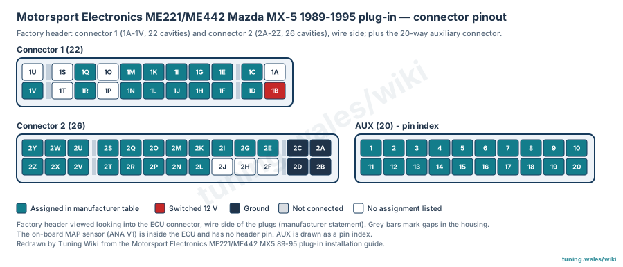
The Motorsport Electronics ME221 and ME442 plug-in ECUs for the early two-plug Mazda MX-5 (NA, 1989–1995) use the factory ECU header, made up of connector 1 (22 cavities, 1A–1V) and connector 2 (26 cavities, 2A–2Z), plus a 20-way auxiliary connector inside the ECU (Molex Mini-Fit Jr 39-01-2205). The manufacturer draws the header looking into the ECU connector from the wire side of the plugs; each plug has two rows divided into three groups by gaps in the housing. The on-board MAP sensor (ANA V1) is inside the ECU and has no header pin.
Pin assignments
Connector 1 carries the ignition 12 V feed (1B), early fuel pump (1C), coil outputs for cylinders 1&4 and 2&3 (1G, 1H), check-engine light, spare low side, air-con relay and switch, primary fan relays for 1.6 and 1.8 engines (1R, 1L), vehicle speed, clutch switch, a VTPS 5 V reference and an alternative tachometer output (1F). Auxiliary DBW motor − (1I) and EGT (1K) positions are not used by the OEM and apply to the ME442 only, depending on DBW version. Connector 2 carries the grounds (2A–2D), crank and cam CAS inputs (2E, 2G), injectors (2U, 2V, 2Y, 2Z; before 1993 injectors are paired on 2U and 2V), throttle position (2L, and 2M after 1994), O2, airflow, intake-air and coolant temperature, the 5 V reference, idle and purge/boost outputs, the 1993-on fuel pump relay (2T), DBW + (2R) and a 12 V output for coil-pack-driven tachometers (2I).
The auxiliary connector provides injectors 5 to 8 (3.5 A, protected), coil 3 and 4 TTL outputs, low sides LS1 to LS3, a knock input, digital inputs 1 to 3, analogue inputs 5 to 7, CAN 1 (120 Ω terminated), a 5 V reference and knock/sensor ground. Model-specific notes from the guide are attached to the affected pins: the late-1995 tachometer jumper, the late-1995 crank-sensor wire that may need moving from 2F to 2E, and confirming the primary-fan output in test mode. Assignments are manufacturer documentation (graded confirmed); cavities without a listed assignment are shown without a function. See the hubs for the ME221 and ME442 MX-5 1989–1995 plug-ins.
Diagram redrawn by Tuning Wiki from the Motorsport Electronics ME221/ME442 MX5 89-95 plug-in installation guide.
Sources
- Motorsport Electronics Limited, ME221/ME442 MX5 89-95 Plug-In installation guide (PDF, uploaded May 2025), Appendix A (OEM header connectivity and drawing), Appendix B (auxiliary connector) and Appendix C (model specifics). Manufacturer documentation. Accessed 19 November 2026.
Connector pinout
Motorsport Electronics ME221 and ME442 plug-in ECUs for the Mazda MX-5 (NA) 1989-1995, two-plug factory header (1A-1V, 2A-2Z) plus the 20-way auxiliary connector. Functions from the manufacturer installation guide, Appendices A and B; cavities without a listed assignment are shown without a function. Header drawn wire side as stated by the manufacturer.
View orientation is stated beside each photograph. Unknown functions remain in the pin index.
Factory connector 1 (22 cavities, 1A-1V)
View: Looking into the ECU connector, wire side of the plugs (manufacturer statement)
Select a pin in a photograph or the index to highlight it.
| Pin | Function / cavity | Confidence / source | Notes |
|---|---|---|---|
| Unknown function Cavity: Unknown |
Unknown | ||
| Unknown function Cavity: Unknown |
Unknown | ||
| Air-con switch / DIGIN 5 Cavity: Populated |
Confirmed ME MX5 89-95 guide, App. A |
||
| Unknown function Cavity: Unknown |
Unknown | ||
| Vehicle speed / DIGIN 4 Cavity: Populated |
Confirmed ME MX5 89-95 guide, App. A |
||
| EGT K-type + / EGT1 (auxiliary) Cavity: Populated |
Confirmed ME MX5 89-95 guide, App. A |
Not used by the OEM; ME442 variant only; depends on DBW version. | |
| DBW motor - (auxiliary) Cavity: Populated |
Confirmed ME MX5 89-95 guide, App. A |
Not used by the OEM; ME442 variant only; depends on DBW version. | |
| Ignition 1 & 4 / coil 1 Cavity: Populated |
Confirmed ME MX5 89-95 guide, App. A |
||
| Check-engine light / LS11 Cavity: Populated |
Confirmed ME MX5 89-95 guide, App. A |
||
| Fuel pump (early cars) Cavity: Populated |
Confirmed ME MX5 89-95 guide, App. A |
||
| Unknown function Cavity: Unknown |
Unknown | ||
| Clutch switch / DIGIN 6 Cavity: Populated |
Confirmed ME MX5 89-95 guide, App. A |
||
| Unknown function Cavity: Unknown |
Unknown | ||
| Primary fan relay (1.6 engines) / LS13 Cavity: Populated |
Confirmed ME MX5 89-95 guide, App. A |
Confirm the correct primary-fan output in MEITE test mode. | |
| Unknown function Cavity: Unknown |
Unknown | ||
| VTPS 5 V reference (via VTPS DIP switch) Cavity: Populated |
Confirmed ME MX5 89-95 guide, App. A |
||
| Primary fan relay (1.8 engines) / LS12 Cavity: Populated |
Confirmed ME MX5 89-95 guide, App. A |
Confirm the correct primary-fan output in MEITE test mode. | |
| Air-con relay / LS15 Cavity: Populated |
Confirmed ME MX5 89-95 guide, App. A |
||
| Ignition 2 & 3 / coil 2 Cavity: Populated |
Confirmed ME MX5 89-95 guide, App. A |
||
| Alternative tachometer output Cavity: Populated |
Confirmed ME MX5 89-95 guide, App. A |
Used on some late-1995 cars after bridging the "ODD TACH" solder jumper on the ECU underside. | |
| Spare low side / LS4 Cavity: Populated |
Confirmed ME MX5 89-95 guide, App. A |
||
| Ignition 12 V Cavity: Populated |
Confirmed ME MX5 89-95 guide, App. A |
Factory connector 2 (26 cavities, 2A-2Z)
View: Looking into the ECU connector, wire side of the plugs (manufacturer statement)
Select a pin in a photograph or the index to highlight it.
| Pin | Function / cavity | Confidence / source | Notes |
|---|---|---|---|
| Injector 3 Cavity: Populated |
Confirmed ME MX5 89-95 guide, App. A |
||
| PWM idle valve / LS9 Cavity: Populated |
Confirmed ME MX5 89-95 guide, App. A |
||
| Injector 1 (and 3 before 1993) Cavity: Populated |
Confirmed ME MX5 89-95 guide, App. A |
||
| Air-con blower relay (1995) / LS16 Cavity: Populated |
Confirmed ME MX5 89-95 guide, App. A |
||
| Coolant temperature / ANA T2 Cavity: Populated |
Confirmed ME MX5 89-95 guide, App. A |
||
| Airflow signal / ANA V4 Cavity: Populated |
Confirmed ME MX5 89-95 guide, App. A |
||
| TPS signal (cars after 1994) Cavity: Populated |
Confirmed ME MX5 89-95 guide, App. A |
||
| 5 V reference Cavity: Populated |
Confirmed ME MX5 89-95 guide, App. A |
||
| 12 V output for four-pin coil-pack-driven tachometer Cavity: Populated |
Confirmed ME MX5 89-95 guide, App. A |
||
| CAS sensor signal / VR cam A Cavity: Populated |
Confirmed ME MX5 89-95 guide, App. A |
||
| CAS sensor signal / VR crank Cavity: Populated |
Confirmed ME MX5 89-95 guide, App. A |
Some late-1995 two-plug cars have a CAS wire in 2F instead; the manufacturer advises moving it to 2E. | |
| Ground Cavity: Populated |
Confirmed ME MX5 89-95 guide, App. A |
||
| Ground Cavity: Populated |
Confirmed ME MX5 89-95 guide, App. A |
||
| Injector 4 Cavity: Populated |
Confirmed ME MX5 89-95 guide, App. A |
||
| Purge / boost solenoid / LS10 Cavity: Populated |
Confirmed ME MX5 89-95 guide, App. A |
||
| Injector 2 (and 4 before 1993) Cavity: Populated |
Confirmed ME MX5 89-95 guide, App. A |
||
| Fuel pump relay (1993 on) / LS14 Cavity: Populated |
Confirmed ME MX5 89-95 guide, App. A |
||
| DBW + Cavity: Populated |
Confirmed ME MX5 89-95 guide, App. A |
||
| Inlet air temperature / ANA T1 Cavity: Populated |
Confirmed ME MX5 89-95 guide, App. A |
||
| O2 sensor signal / ANA V3 Cavity: Populated |
Confirmed ME MX5 89-95 guide, App. A |
||
| TPS signal / ANA V2 Cavity: Populated |
Confirmed ME MX5 89-95 guide, App. A |
||
| Unknown function Cavity: Unknown |
Unknown | ||
| Unknown function Cavity: Unknown |
Unknown | ||
| Unknown function Cavity: Unknown |
Unknown | Some late-1995 two-plug cars carry a CAS wire here; the manufacturer advises moving it to 2E. | |
| Ground Cavity: Populated |
Confirmed ME MX5 89-95 guide, App. A |
||
| Ground Cavity: Populated |
Confirmed ME MX5 89-95 guide, App. A |
Auxiliary connector (20-way Molex Mini-Fit Jr 39-01-2205)
View: Pin index (2 x 10); see manufacturer drawing for orientation
Select a pin in a photograph or the index to highlight it.
| Pin | Function / cavity | Confidence / source | Notes |
|---|---|---|---|
| Injector 5 (3.5 A, protected) Cavity: Populated |
Confirmed ME MX5 89-95 guide, App. B |
||
| Injector 6 (3.5 A, protected) Cavity: Populated |
Confirmed ME MX5 89-95 guide, App. B |
||
| Injector 7 (3.5 A, protected) Cavity: Populated |
Confirmed ME MX5 89-95 guide, App. B |
||
| Injector 8 (3.5 A, protected) Cavity: Populated |
Confirmed ME MX5 89-95 guide, App. B |
||
| Coil 3 (50 mA TTL output) Cavity: Populated |
Confirmed ME MX5 89-95 guide, App. B |
||
| Coil 4 (50 mA TTL output) Cavity: Populated |
Confirmed ME MX5 89-95 guide, App. B |
||
| LS1 low-side output (2 A, PWM-capable) Cavity: Populated |
Confirmed ME MX5 89-95 guide, App. B |
||
| LS2 low-side output (2 A, PWM-capable) Cavity: Populated |
Confirmed ME MX5 89-95 guide, App. B |
||
| LS3 low-side output (2 A, PWM-capable) Cavity: Populated |
Confirmed ME MX5 89-95 guide, App. B |
||
| Knock signal Cavity: Populated |
Confirmed ME MX5 89-95 guide, App. B |
EGT on the ME442 8995 needs specific instructions from the manufacturer. | |
| Digital input 1 (1 kOhm 5 V pull-up) Cavity: Populated |
Confirmed ME MX5 89-95 guide, App. B |
||
| Digital input 2 (1 kOhm 5 V pull-up) Cavity: Populated |
Confirmed ME MX5 89-95 guide, App. B |
||
| Digital input 3 (1 kOhm 5 V pull-up) Cavity: Populated |
Confirmed ME MX5 89-95 guide, App. B |
||
| Analogue volt 5 (0-5 V input) Cavity: Populated |
Confirmed ME MX5 89-95 guide, App. B |
||
| Analogue volt 6 (0-5 V input) Cavity: Populated |
Confirmed ME MX5 89-95 guide, App. B |
||
| Analogue volt 7 (0-5 V input) Cavity: Populated |
Confirmed ME MX5 89-95 guide, App. B |
||
| CAN 1 low (120 ohm terminated) Cavity: Populated |
Confirmed ME MX5 89-95 guide, App. B |
||
| CAN 1 high (120 ohm terminated) Cavity: Populated |
Confirmed ME MX5 89-95 guide, App. B |
||
| 5 V reference (100 mA max) Cavity: Populated |
Confirmed ME MX5 89-95 guide, App. B |
||
| Knock and sensor ground Cavity: Populated |
Confirmed ME MX5 89-95 guide, App. B |