Tuning Wiki

This is a historical revision. Read the current page or return to its history.

Page organisation in this revision
Page type
Technical article
Subject
Engine ECU
Parent
MaxxECU Toyota Supra MKIV (2JZ) plug-in adapter
Applies to
MaxxECU Toyota Supra MKIV (2JZ) plug-in adapter
Tool groups
None
Manufacturers
MaxxECU, Toyota

Changes from revision 1 to revision 1

Removed text is struck through; added text is highlighted.

Connectors covered

The MaxxECU GEN1 plug-in adapter for the Toyota Supra MKIV (2JZ) fits MaxxECU V1, RACE and PRO units, and according to the guide the STREET with some rewiring. Besides the factory-loom plug, the adapter carries a 16-pin extra connector and a 3-pin connector for analogue input 4; the wideband lambda sensor is wired through a pre-wired 6-pin connector for a Bosch LSU 4.2 sensor. This article covers 25 pins: 16 on the extra connector, 6 on the sensor connector and 3 on the analogue input connector. The factory ECU connector is not covered.

16-pin extra connector

The manufacturer's guide draws the 16-pin connector from the wire side of the pre-wired harness, with pins 1 to 8 on the upper row and 9 to 16 on the lower row; the cavities also carry letters (H to A on the upper row, S to J on the lower). Pins 1, 2, 3, 4, 9 and 10 carry the wideband lambda signals. The other assignments are pin 5, GPO 6 output; pin 6, GPO 7 / DIN 3 output or digital input; pin 8, INJ 7 output; pin 11, +12 V output; pin 12, +12 V output; pin 13, engine ground; pin 14, AIN 1 temperature input; pin 15, AIN 2 temperature input; pin 16, AIN 3 (0-5 V analogue input). The guide lists no function for pin 7.

Wideband sensor and analogue input connectors

The 6-pin LSU 4.2 sensor connector, also seen from the wire side, carries VS on pin 1, RCAL on 2, heater +12 V on 3, heater H- on 4, VREF on 5 and IP on 6. The 3-pin connector has sensor ground on pin 1, analogue input 4 (0-5 V) on pin 2 and the +5 V sensor supply on pin 3; the guide does not draw its face, so the diagram gives it as a pin index only.

The guide is manufacturer documentation. Pin assignments should be checked against the adapter revision and the MaxxECU unit before wiring.
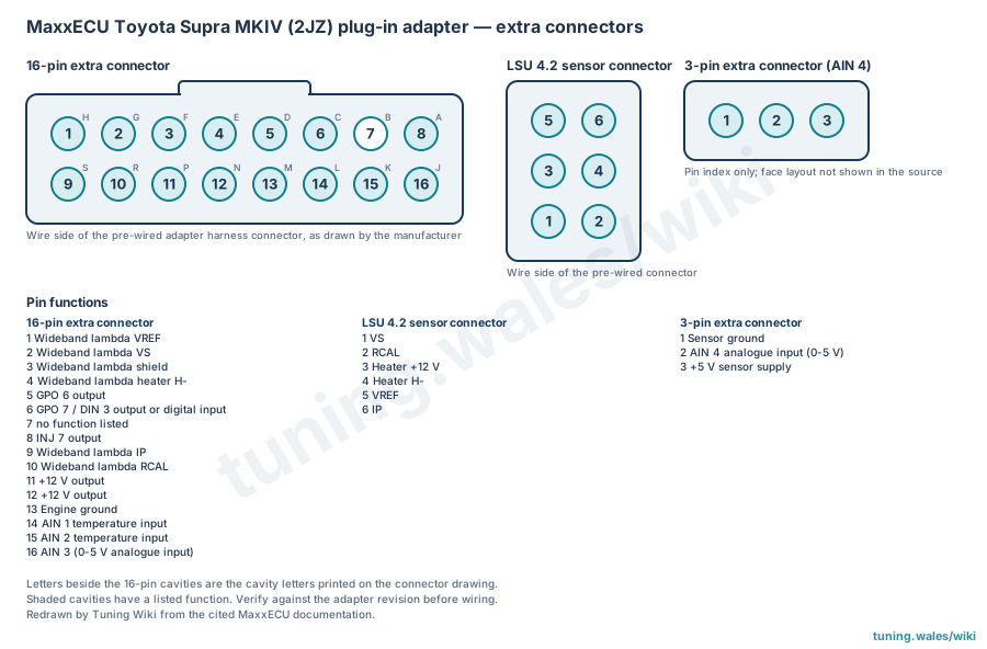
Extra connectors of the MaxxECU Toyota Supra MKIV (2JZ) adapter. Diagram redrawn by Tuning Wiki from the MaxxECU installation guide.

Sources

Toyota Supra MKIV (2JZ), MaxxECU documentation (manufacturer installation guide). Accessed 19 November 2026.

Rendered revisions

Open each version to inspect formatting, tables and photographs.

Revision 1: MaxxECU Toyota Supra MKIV (2JZ) plug-in adapter connector pinout

Connectors covered

The MaxxECU GEN1 plug-in adapter for the Toyota Supra MKIV (2JZ) fits MaxxECU V1, RACE and PRO units, and according to the guide the STREET with some rewiring. Besides the factory-loom plug, the adapter carries a 16-pin extra connector and a 3-pin connector for analogue input 4; the wideband lambda sensor is wired through a pre-wired 6-pin connector for a Bosch LSU 4.2 sensor. This article covers 25 pins: 16 on the extra connector, 6 on the sensor connector and 3 on the analogue input connector. The factory ECU connector is not covered.

16-pin extra connector

The manufacturer's guide draws the 16-pin connector from the wire side of the pre-wired harness, with pins 1 to 8 on the upper row and 9 to 16 on the lower row; the cavities also carry letters (H to A on the upper row, S to J on the lower). Pins 1, 2, 3, 4, 9 and 10 carry the wideband lambda signals. The other assignments are pin 5, GPO 6 output; pin 6, GPO 7 / DIN 3 output or digital input; pin 8, INJ 7 output; pin 11, +12 V output; pin 12, +12 V output; pin 13, engine ground; pin 14, AIN 1 temperature input; pin 15, AIN 2 temperature input; pin 16, AIN 3 (0-5 V analogue input). The guide lists no function for pin 7.

Wideband sensor and analogue input connectors

The 6-pin LSU 4.2 sensor connector, also seen from the wire side, carries VS on pin 1, RCAL on 2, heater +12 V on 3, heater H- on 4, VREF on 5 and IP on 6. The 3-pin connector has sensor ground on pin 1, analogue input 4 (0-5 V) on pin 2 and the +5 V sensor supply on pin 3; the guide does not draw its face, so the diagram gives it as a pin index only.

The guide is manufacturer documentation. Pin assignments should be checked against the adapter revision and the MaxxECU unit before wiring.

MaxxECU Toyota Supra MKIV (2JZ) plug-in adapter extra connectors
Extra connectors of the MaxxECU Toyota Supra MKIV (2JZ) adapter. Diagram redrawn by Tuning Wiki from the MaxxECU installation guide.

Sources

Connector pinout

Applicability

MaxxECU GEN1 plug-in adapter for Toyota Supra MKIV (2JZ), for MaxxECU V1, RACE and PRO (and the STREET with some rewiring, according to the guide). Covers the adapter's 16-pin extra connector, the pre-wired 6-pin Bosch LSU 4.2 wideband sensor connector and the 3-pin analogue input 4 connector, from the manufacturer's installation guide. The factory ECU connector pinout is not covered. Connectors viewed from the wire side; the 3-pin connector is a pin index only.

View orientation is stated beside each photograph. Unknown functions remain in the pin index.

16-pin extra connector (adapter)

Redrawn connector face
View: Wire side of the pre-wired adapter harness connector, as drawn by the manufacturer
16-pin extra connector (adapter) — Redrawn connector face. Wire side of the pre-wired adapter harness connector, as drawn by the manufacturer

Select a pin in a photograph or the index to highlight it.

16-pin extra connector (adapter) — complete pin index
PinFunction / cavityConfidence / sourceNotes
Wideband lambda VREF
Cavity: Populated
Confirmed

MaxxECU Supra 2JZ plug-in guide

Wideband lambda VS
Cavity: Populated
Confirmed

MaxxECU Supra 2JZ plug-in guide

Wideband lambda shield
Cavity: Populated
Confirmed

MaxxECU Supra 2JZ plug-in guide

Wideband lambda heater H-
Cavity: Populated
Confirmed

MaxxECU Supra 2JZ plug-in guide

GPO 6 output
Cavity: Populated
Confirmed

MaxxECU Supra 2JZ plug-in guide

GPO 7 / DIN 3 output or digital input
Cavity: Populated
Confirmed

MaxxECU Supra 2JZ plug-in guide

Unknown function
Cavity: Unknown
Unknown No function listed in the manufacturer table.
INJ 7 output
Cavity: Populated
Confirmed

MaxxECU Supra 2JZ plug-in guide

Wideband lambda IP
Cavity: Populated
Confirmed

MaxxECU Supra 2JZ plug-in guide

Wideband lambda RCAL
Cavity: Populated
Confirmed

MaxxECU Supra 2JZ plug-in guide

+12 V output
Cavity: Populated
Confirmed

MaxxECU Supra 2JZ plug-in guide

+12 V output
Cavity: Populated
Confirmed

MaxxECU Supra 2JZ plug-in guide

Engine ground
Cavity: Populated
Confirmed

MaxxECU Supra 2JZ plug-in guide

AIN 1 temperature input
Cavity: Populated
Confirmed

MaxxECU Supra 2JZ plug-in guide

AIN 2 temperature input
Cavity: Populated
Confirmed

MaxxECU Supra 2JZ plug-in guide

AIN 3 (0-5 V analogue input)
Cavity: Populated
Confirmed

MaxxECU Supra 2JZ plug-in guide

Wideband sensor connector (Bosch LSU 4.2, 6-pin)

Redrawn connector face
View: Wire side of the pre-wired connector
Wideband sensor connector (Bosch LSU 4.2, 6-pin) — Redrawn connector face. Wire side of the pre-wired connector

Select a pin in a photograph or the index to highlight it.

Wideband sensor connector (Bosch LSU 4.2, 6-pin) — complete pin index
PinFunction / cavityConfidence / sourceNotes
VREF
Cavity: Populated
Confirmed

MaxxECU Supra 2JZ plug-in guide

IP
Cavity: Populated
Confirmed

MaxxECU Supra 2JZ plug-in guide

Heater +12 V
Cavity: Populated
Confirmed

MaxxECU Supra 2JZ plug-in guide

Heater H-
Cavity: Populated
Confirmed

MaxxECU Supra 2JZ plug-in guide

VS
Cavity: Populated
Confirmed

MaxxECU Supra 2JZ plug-in guide

RCAL
Cavity: Populated
Confirmed

MaxxECU Supra 2JZ plug-in guide

3-pin extra connector (analogue input 4)

Redrawn connector face
View: Pin index only; face layout not shown in the source
3-pin extra connector (analogue input 4) — Redrawn connector face. Pin index only; face layout not shown in the source

Select a pin in a photograph or the index to highlight it.

3-pin extra connector (analogue input 4) — complete pin index
PinFunction / cavityConfidence / sourceNotes
Sensor ground
Cavity: Populated
Confirmed

MaxxECU Supra 2JZ plug-in guide

AIN 4 analogue input (0-5 V)
Cavity: Populated
Confirmed

MaxxECU Supra 2JZ plug-in guide

+5 V sensor supply
Cavity: Populated
Confirmed

MaxxECU Supra 2JZ plug-in guide

Revision 1: MaxxECU Toyota Supra MKIV (2JZ) plug-in adapter connector pinout

Connectors covered

The MaxxECU GEN1 plug-in adapter for the Toyota Supra MKIV (2JZ) fits MaxxECU V1, RACE and PRO units, and according to the guide the STREET with some rewiring. Besides the factory-loom plug, the adapter carries a 16-pin extra connector and a 3-pin connector for analogue input 4; the wideband lambda sensor is wired through a pre-wired 6-pin connector for a Bosch LSU 4.2 sensor. This article covers 25 pins: 16 on the extra connector, 6 on the sensor connector and 3 on the analogue input connector. The factory ECU connector is not covered.

16-pin extra connector

The manufacturer's guide draws the 16-pin connector from the wire side of the pre-wired harness, with pins 1 to 8 on the upper row and 9 to 16 on the lower row; the cavities also carry letters (H to A on the upper row, S to J on the lower). Pins 1, 2, 3, 4, 9 and 10 carry the wideband lambda signals. The other assignments are pin 5, GPO 6 output; pin 6, GPO 7 / DIN 3 output or digital input; pin 8, INJ 7 output; pin 11, +12 V output; pin 12, +12 V output; pin 13, engine ground; pin 14, AIN 1 temperature input; pin 15, AIN 2 temperature input; pin 16, AIN 3 (0-5 V analogue input). The guide lists no function for pin 7.

Wideband sensor and analogue input connectors

The 6-pin LSU 4.2 sensor connector, also seen from the wire side, carries VS on pin 1, RCAL on 2, heater +12 V on 3, heater H- on 4, VREF on 5 and IP on 6. The 3-pin connector has sensor ground on pin 1, analogue input 4 (0-5 V) on pin 2 and the +5 V sensor supply on pin 3; the guide does not draw its face, so the diagram gives it as a pin index only.

The guide is manufacturer documentation. Pin assignments should be checked against the adapter revision and the MaxxECU unit before wiring.

MaxxECU Toyota Supra MKIV (2JZ) plug-in adapter extra connectors
Extra connectors of the MaxxECU Toyota Supra MKIV (2JZ) adapter. Diagram redrawn by Tuning Wiki from the MaxxECU installation guide.

Sources

Connector pinout

Applicability

MaxxECU GEN1 plug-in adapter for Toyota Supra MKIV (2JZ), for MaxxECU V1, RACE and PRO (and the STREET with some rewiring, according to the guide). Covers the adapter's 16-pin extra connector, the pre-wired 6-pin Bosch LSU 4.2 wideband sensor connector and the 3-pin analogue input 4 connector, from the manufacturer's installation guide. The factory ECU connector pinout is not covered. Connectors viewed from the wire side; the 3-pin connector is a pin index only.

View orientation is stated beside each photograph. Unknown functions remain in the pin index.

16-pin extra connector (adapter)

Redrawn connector face
View: Wire side of the pre-wired adapter harness connector, as drawn by the manufacturer
16-pin extra connector (adapter) — Redrawn connector face. Wire side of the pre-wired adapter harness connector, as drawn by the manufacturer

Select a pin in a photograph or the index to highlight it.

16-pin extra connector (adapter) — complete pin index
PinFunction / cavityConfidence / sourceNotes
Wideband lambda VREF
Cavity: Populated
Confirmed

MaxxECU Supra 2JZ plug-in guide

Wideband lambda VS
Cavity: Populated
Confirmed

MaxxECU Supra 2JZ plug-in guide

Wideband lambda shield
Cavity: Populated
Confirmed

MaxxECU Supra 2JZ plug-in guide

Wideband lambda heater H-
Cavity: Populated
Confirmed

MaxxECU Supra 2JZ plug-in guide

GPO 6 output
Cavity: Populated
Confirmed

MaxxECU Supra 2JZ plug-in guide

GPO 7 / DIN 3 output or digital input
Cavity: Populated
Confirmed

MaxxECU Supra 2JZ plug-in guide

Unknown function
Cavity: Unknown
Unknown No function listed in the manufacturer table.
INJ 7 output
Cavity: Populated
Confirmed

MaxxECU Supra 2JZ plug-in guide

Wideband lambda IP
Cavity: Populated
Confirmed

MaxxECU Supra 2JZ plug-in guide

Wideband lambda RCAL
Cavity: Populated
Confirmed

MaxxECU Supra 2JZ plug-in guide

+12 V output
Cavity: Populated
Confirmed

MaxxECU Supra 2JZ plug-in guide

+12 V output
Cavity: Populated
Confirmed

MaxxECU Supra 2JZ plug-in guide

Engine ground
Cavity: Populated
Confirmed

MaxxECU Supra 2JZ plug-in guide

AIN 1 temperature input
Cavity: Populated
Confirmed

MaxxECU Supra 2JZ plug-in guide

AIN 2 temperature input
Cavity: Populated
Confirmed

MaxxECU Supra 2JZ plug-in guide

AIN 3 (0-5 V analogue input)
Cavity: Populated
Confirmed

MaxxECU Supra 2JZ plug-in guide

Wideband sensor connector (Bosch LSU 4.2, 6-pin)

Redrawn connector face
View: Wire side of the pre-wired connector
Wideband sensor connector (Bosch LSU 4.2, 6-pin) — Redrawn connector face. Wire side of the pre-wired connector

Select a pin in a photograph or the index to highlight it.

Wideband sensor connector (Bosch LSU 4.2, 6-pin) — complete pin index
PinFunction / cavityConfidence / sourceNotes
VREF
Cavity: Populated
Confirmed

MaxxECU Supra 2JZ plug-in guide

IP
Cavity: Populated
Confirmed

MaxxECU Supra 2JZ plug-in guide

Heater +12 V
Cavity: Populated
Confirmed

MaxxECU Supra 2JZ plug-in guide

Heater H-
Cavity: Populated
Confirmed

MaxxECU Supra 2JZ plug-in guide

VS
Cavity: Populated
Confirmed

MaxxECU Supra 2JZ plug-in guide

RCAL
Cavity: Populated
Confirmed

MaxxECU Supra 2JZ plug-in guide

3-pin extra connector (analogue input 4)

Redrawn connector face
View: Pin index only; face layout not shown in the source
3-pin extra connector (analogue input 4) — Redrawn connector face. Pin index only; face layout not shown in the source

Select a pin in a photograph or the index to highlight it.

3-pin extra connector (analogue input 4) — complete pin index
PinFunction / cavityConfidence / sourceNotes
Sensor ground
Cavity: Populated
Confirmed

MaxxECU Supra 2JZ plug-in guide

AIN 4 analogue input (0-5 V)
Cavity: Populated
Confirmed

MaxxECU Supra 2JZ plug-in guide

+5 V sensor supply
Cavity: Populated
Confirmed

MaxxECU Supra 2JZ plug-in guide