Connectors covered
The MaxxECU GEN1 plug-in adapter for the Toyota Supra MKIV (2JZ) fits MaxxECU V1, RACE and PRO units, and according to the guide the STREET with some rewiring. Besides the factory-loom plug, the adapter carries a 16-pin extra connector and a 3-pin connector for analogue input 4; the wideband lambda sensor is wired through a pre-wired 6-pin connector for a Bosch LSU 4.2 sensor. This article covers 25 pins: 16 on the extra connector, 6 on the sensor connector and 3 on the analogue input connector. The factory ECU connector is not covered.
16-pin extra connector
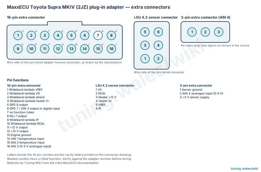
The manufacturer's guide draws the 16-pin connector from the wire side of the pre-wired harness, with pins 1 to 8 on the upper row and 9 to 16 on the lower row; the cavities also carry letters (H to A on the upper row, S to J on the lower). Pins 1, 2, 3, 4, 9 and 10 carry the wideband lambda signals. The other assignments are pin 5, GPO 6 output; pin 6, GPO 7 / DIN 3 output or digital input; pin 8, INJ 7 output; pin 11, +12 V output; pin 12, +12 V output; pin 13, engine ground; pin 14, AIN 1 temperature input; pin 15, AIN 2 temperature input; pin 16, AIN 3 (0-5 V analogue input). The guide lists no function for pin 7.
Wideband sensor and analogue input connectors
The 6-pin LSU 4.2 sensor connector, also seen from the wire side, carries VS on pin 1, RCAL on 2, heater +12 V on 3, heater H- on 4, VREF on 5 and IP on 6. The 3-pin connector has sensor ground on pin 1, analogue input 4 (0-5 V) on pin 2 and the +5 V sensor supply on pin 3; the guide does not draw its face, so the diagram gives it as a pin index only.
The guide is manufacturer documentation. Pin assignments should be checked against the adapter revision and the MaxxECU unit before wiring.
Sources
- Toyota Supra MKIV (2JZ), MaxxECU documentation (manufacturer installation guide). Accessed 19 November 2026.
Connector pinout
MaxxECU GEN1 plug-in adapter for Toyota Supra MKIV (2JZ), for MaxxECU V1, RACE and PRO (and the STREET with some rewiring, according to the guide). Covers the adapter's 16-pin extra connector, the pre-wired 6-pin Bosch LSU 4.2 wideband sensor connector and the 3-pin analogue input 4 connector, from the manufacturer's installation guide. The factory ECU connector pinout is not covered. Connectors viewed from the wire side; the 3-pin connector is a pin index only.
View orientation is stated beside each photograph. Unknown functions remain in the pin index.
16-pin extra connector (adapter)
View: Wire side of the pre-wired adapter harness connector, as drawn by the manufacturer
Select a pin in a photograph or the index to highlight it.
| Pin | Function / cavity | Confidence / source | Notes |
|---|---|---|---|
| Wideband lambda VREF Cavity: Populated |
Confirmed MaxxECU Supra 2JZ plug-in guide |
||
| Wideband lambda VS Cavity: Populated |
Confirmed MaxxECU Supra 2JZ plug-in guide |
||
| Wideband lambda shield Cavity: Populated |
Confirmed MaxxECU Supra 2JZ plug-in guide |
||
| Wideband lambda heater H- Cavity: Populated |
Confirmed MaxxECU Supra 2JZ plug-in guide |
||
| GPO 6 output Cavity: Populated |
Confirmed MaxxECU Supra 2JZ plug-in guide |
||
| GPO 7 / DIN 3 output or digital input Cavity: Populated |
Confirmed MaxxECU Supra 2JZ plug-in guide |
||
| Unknown function Cavity: Unknown |
Unknown | No function listed in the manufacturer table. | |
| INJ 7 output Cavity: Populated |
Confirmed MaxxECU Supra 2JZ plug-in guide |
||
| Wideband lambda IP Cavity: Populated |
Confirmed MaxxECU Supra 2JZ plug-in guide |
||
| Wideband lambda RCAL Cavity: Populated |
Confirmed MaxxECU Supra 2JZ plug-in guide |
||
| +12 V output Cavity: Populated |
Confirmed MaxxECU Supra 2JZ plug-in guide |
||
| +12 V output Cavity: Populated |
Confirmed MaxxECU Supra 2JZ plug-in guide |
||
| Engine ground Cavity: Populated |
Confirmed MaxxECU Supra 2JZ plug-in guide |
||
| AIN 1 temperature input Cavity: Populated |
Confirmed MaxxECU Supra 2JZ plug-in guide |
||
| AIN 2 temperature input Cavity: Populated |
Confirmed MaxxECU Supra 2JZ plug-in guide |
||
| AIN 3 (0-5 V analogue input) Cavity: Populated |
Confirmed MaxxECU Supra 2JZ plug-in guide |
Wideband sensor connector (Bosch LSU 4.2, 6-pin)
View: Wire side of the pre-wired connector
Select a pin in a photograph or the index to highlight it.
| Pin | Function / cavity | Confidence / source | Notes |
|---|---|---|---|
| VREF Cavity: Populated |
Confirmed MaxxECU Supra 2JZ plug-in guide |
||
| IP Cavity: Populated |
Confirmed MaxxECU Supra 2JZ plug-in guide |
||
| Heater +12 V Cavity: Populated |
Confirmed MaxxECU Supra 2JZ plug-in guide |
||
| Heater H- Cavity: Populated |
Confirmed MaxxECU Supra 2JZ plug-in guide |
||
| VS Cavity: Populated |
Confirmed MaxxECU Supra 2JZ plug-in guide |
||
| RCAL Cavity: Populated |
Confirmed MaxxECU Supra 2JZ plug-in guide |
3-pin extra connector (analogue input 4)
View: Pin index only; face layout not shown in the source
Select a pin in a photograph or the index to highlight it.
| Pin | Function / cavity | Confidence / source | Notes |
|---|---|---|---|
| Sensor ground Cavity: Populated |
Confirmed MaxxECU Supra 2JZ plug-in guide |
||
| AIN 4 analogue input (0-5 V) Cavity: Populated |
Confirmed MaxxECU Supra 2JZ plug-in guide |
||
| +5 V sensor supply Cavity: Populated |
Confirmed MaxxECU Supra 2JZ plug-in guide |