What is KE-Jetronic?
Bosch KE-Jetronic combines the continuous, mechanically metered injection principle of K-Jetronic with electronic correction through an electro-hydraulic pressure actuator. An airflow sensor plate and fuel distributor still determine the basic fuel delivery; the ECU changes the hydraulic metering conditions to correct it. The main injectors are mechanical continuous-flow valves, not electronically pulsed solenoids. Bosch's technical instruction describes a lambda-controlled KE system, but the equipment and functions of individual applications vary. [1, 2]
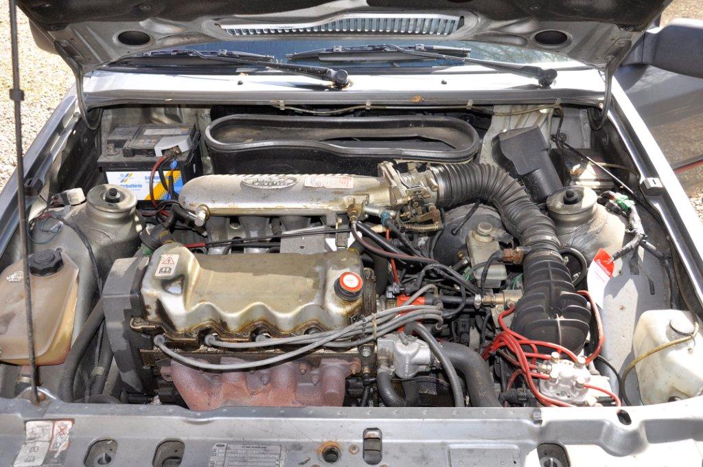

How it works
- An electric pump supplies pressurised fuel to the distributor. Intake air moves the sensor plate; a linked plunger exposes the distributor's metering slits and establishes the basic fuel quantity.
- The distributor feeds a separate line and pressure-operated injector for each cylinder. The injector needle opens hydraulically and sprays continuously into the intake port while adequate fuel flow and pressure are present.
- The ECU receives signals that can include engine temperature, throttle position or switches, engine speed and airflow-plate position. The exact sensor set depends on the installation.
- The ECU sends current to the electro-hydraulic actuator (EHA), mounted on the fuel distributor in the Bosch-described design. It changes pressures in the distributor's differential-pressure circuits, altering the pressure drop at the metering slits and hence the delivered fuel quantity. [1]
Electronic corrections and lambda
Depending on the system, electronic corrections can cover warm-up, acceleration and full load; Bosch also describes overrun fuel cut-off and engine-speed limiting. In the Bosch-described KE system, electronically controlled pressure correction performs warm-up enrichment rather than relying on the conventional K-Jetronic warm-up regulator. Do not assume every vehicle has an identical component list or strategy. [1, 2]
Where lambda control is fitted and active, the oxygen sensor reports whether the exhaust mixture is rich or lean around lambda 1. The ECU adjusts the actuator current to correct fuel delivery, supporting a three-way catalyst. During warm-up or other operating modes, a particular vehicle may use different control logic: use its own service information. [1]
Injectors: what changes from K and D?
KE's main injector is still a spring-loaded, pressure-opening mechanical valve. It does not decide the fuel quantity by an electrical opening time; the fuel distributor meters it. Some continuous-injection valves are air-shrouded to aid atomisation. A separate electrical cold-start valve may be fitted, so an electrical connector on that valve is not evidence that the main injectors are electronic. [1]
K-Jetronic with lambda uses a pulsed frequency valve to correct the hydraulic circuit, whereas KE-Jetronic uses an ECU-controlled electro-hydraulic pressure actuator. Both retain continuous mechanical main injectors. In D-Jetronic, the ECU instead opens electrically operated main injectors for timed pulses.
Identification and workshop checks
- Identify the engine, market, system and Bosch numbers. An airflow plate and a distributor with individual fuel lines point towards continuous injection; a distributor-mounted electrical pressure actuator is a useful KE clue, but confirm from the vehicle manual.
- Check fuel supply and system pressure, air leaks, ignition condition and the operation of the mechanical metering unit before attributing a fault to the ECU. Use the pressure test points and limits for that exact fuel distributor.
- For the electrical side, check power and grounds, temperature and throttle inputs, airflow-plate position signal where fitted, and the actuator circuit. Sensor and actuator test values and current polarity are vehicle-specific.
- Where fitted, assess lambda feedback under the specified conditions. The Bosch design describes a basic hydraulic operating condition if actuator control current is lost; that is not a guarantee that every vehicle will run normally, or run at all, with an electrical fault.
Follow the vehicle's fuel-pressure release and leak-check procedures before opening connections. Baseline mixture and pressure settings should use the specified equipment and conditions, not generic screw positions.
Sources
- [1] Bosch technical instruction: KE-Jetronic with lambda closed-loop control, independent PDF mirror; metering, continuous injectors, electro-hydraulic actuator and corrections.
- [2] Bosch Classic: gasoline systems, distributor and KE pressure-regulator descriptions. Accessed 10 November 2026.