MaxxECU STREET — Wire-in unit for up to six sequential cylinders, or up to twelve cylinders with wasted spark. MaxxECU product information.
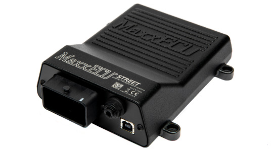
Model identification and capabilities
STREET includes a 400 kPa absolute MAP sensor, an internal controller for an LSU 4.2 or 4.9 wideband sensor, two VR/digital trigger inputs, extra temperature and analogue inputs, and USB tuning. Internal logging is listed as 8 MB. Unlike SPORT, its six injector channels are high-impedance outputs and it has no built-in electronic throttle motor driver. Manufacturer specification; MaxxECU model comparison.
| Sequential cylinders, maximum | 6 |
|---|---|
| Injector outputs | 6 high-impedance |
| Ignition outputs | 6 |
| Configuration | MTune; check the release appropriate to the ECU and hardware revision |
Processor
The manufacturer product page lists an ARM Cortex-M3 main processor running at 120 MHz (manufacturer specification). The specific microcontroller part number is not published.
Identification and installation
The manufacturer requires external current limiting with low-impedance injectors. Connector 1 is shared in shape with other models, but some positions have different functions.
Record the model label, serial number, hardware revision, firmware, connector keying and loom. Outputs can be assigned or share functions; supported functions also depend on available I/O and software configuration. The figure in the comparison is a controller capability, not proof of compatibility with a particular engine or vehicle.
Connector and pinout
Complete 48-way connector 1 positions from the manufacturer’s model-specific column. A dash in the source is shown as not assigned. Consult the drawing for orientation and the remaining connectors. Exact wiring and connector reference.
| Position | Manufacturer function | Notes |
|---|---|---|
| A1 | Not assigned in source | |
| A2 | IGN 1 | |
| A3 | IGN 2 | |
| A4 | GPO 8/TACHO | 660ohm pullup |
| B1 | Not assigned in source | |
| B2 | IGN 3 | |
| B3 | IGN 4 | |
| B4 | GPO 1 | |
| C1 | Not assigned in source | |
| C2 | IGN 5 | |
| C3 | IGN 6 | |
| C4 | GPO 2 | |
| D1 | WBO2 Heater- | |
| D2 | Not assigned in source | |
| D3 | Not assigned in source | |
| D4 | GPO 3 | |
| E1 | CAN H | |
| E2 | CAN L | |
| E3 | GND Shield | |
| E4 | Not assigned in source | |
| F1 | CLT | |
| F2 | IAT | |
| F3 | WBO2 VREF | |
| F4 | WBO2 VS | |
| G1 | +5V sensor supply | (peak 0.5A, max 150mA) |
| G2 | TPS/AIN | |
| G3 | WBO2 IP | |
| G4 | WBO2 RCAL | |
| H1 | Sensor GND | |
| H2 | Trigger GND | |
| H3 | TRIGGER | |
| H4 | HOME | |
| J1 | AIN 1 (temperature) | |
| J2 | AIN 2 (Temperature) | |
| J3 | AIN 3 (0-5V) | |
| J4 | AIN 4 (0-5V) | |
| K1 | INJ 1 | |
| K2 | INJ 2 | |
| K3 | DIN 1 | |
| K4 | DIN 2 | |
| L1 | Not assigned in source | |
| L2 | Not assigned in source | |
| L3 | INJ 6 | |
| L4 | Engine GND | |
| M1 | INJ 3 | |
| M2 | INJ 4 | |
| M3 | INJ 5 | |
| M4 | +12V ECU power supply |
Consult the full diagram for wiring, grounds, supply fuses, driver limits, connector orientation and remaining positions. Sensor grounds and power grounds have different purposes; follow the matching manual.
All positions of the GEN1 connectors, including this unit's, are listed as a structured pin index in MaxxECU GEN1 connector pinout.
Software and further documents
- MaxxECU STREET: product information
- Model wiring and pinout reference
- MTune, quick-start guides and revision-specific wiring downloads
- MaxxECU family overview
Sources reviewed 17 November 2026.