Removed text is struck through; added text is highlighted.
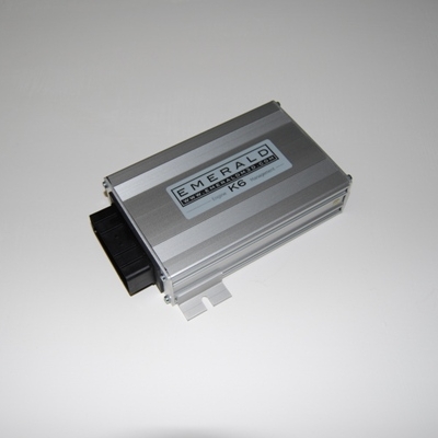
Later Emerald K6+ shown as a family illustration; this page covers an earlier model and its enclosure and connectors may differ. Image: Emerald M3D, reproduced with permission.
Emerald K6 is a 32-bit programmable engine-management ECU introduced in early 2010. Emerald specifies six injection and six ignition drivers, allowing sequential control for up to six cylinders. Emerald K6 specification.
Inputs, outputs and interfaces
Three configurable inductive or digital speed-trigger inputs for crank, cam or distributor.Internal barometric pressure sensor; engine load by TPS and/or 0–5 V MAP signal.Six injector drivers and six configurable ignition drivers. The manufacturer's page describes active-high use with external amplifiers or active-low direct coil control.RS232 communication and CAN 2.0B up to 1 Mbit/s; up to four road-speed inputs.Adaptive lambda uses a suitable external wideband controller with 0–5 V output; K6 also accepts a narrowband signal.
Emerald's specification gives a 6.5–18 V operating supply, 110 × 190 × 44 mm case, IP65 enclosure and IP68 connectors. Features and pins must be checked against the actual hardware and configuration.
Wiring and identification
Obtain the K6 quick-start, configuration guide and K3/K6 manual from Emerald's software and manuals page. Emerald also supplies vehicle-specific adapters; those adapters do not make every factory harness interchangeable. The manufacturer notes that individual units can have bespoke software, so quote the serial number when in doubt.
See Emerald standalone ECUs and the separate K6+ reference.
COMMS nine-way connector
Race Technology’s K3/K6 CAN integration instructions identify the left-hand COMMS connector and the following RS232 and CAN assignments. Check orientation and firmware on the actual ECU; its CAN protocol may require configuration.
The Emerald K6 configuration guide, 1 March 2012, identifies the following positions. This is a partial table: other 36-way cavities and hardware revisions must be checked against the ECU’s own specification.
ECU pinDocumented example4Ignition driver 3 in an appropriate six-cylinder configuration, otherwise potentially main relay control5Ignition driver 2 in the illustrated wasted-spark configuration7Narrowband oxygen sensor signal18Narrowband oxygen sensor signal ground35Common example for a 0–5 V wideband controller signal; other configurable auxiliary inputs are possible36AuxOut36, example narrowband sensor heater control
Structured connector pins
The documented main-connector positions above and the COMMS connector are given as structured pin indexes in Emerald K6 original ECU connector pinout. Emerald's K6 part-loom wiring details also give a complete 36-way table for a drive-by-wire loom, structured in Emerald K6 and K6+ 36-way connector pinout. Emerald's specification describes the K6 as a 32-bit ECU but does not name its microcontroller.
Rendered revisions
Open each version to inspect formatting, tables and photographs.
Revision 4: Emerald K6 original ECULater Emerald K6+ shown as a family illustration; this page covers an earlier model and its enclosure and connectors may differ. Image: Emerald M3D, reproduced with permission.
Emerald K6 is a 32-bit programmable engine-management ECU introduced in early 2010. Emerald specifies six injection and six ignition drivers, allowing sequential control for up to six cylinders. Emerald K6 specification.
Inputs, outputs and interfaces
Three configurable inductive or digital speed-trigger inputs for crank, cam or distributor.
Internal barometric pressure sensor; engine load by TPS and/or 0–5 V MAP signal.
Six injector drivers and six configurable ignition drivers. The manufacturer's page describes active-high use with external amplifiers or active-low direct coil control.
RS232 communication and CAN 2.0B up to 1 Mbit/s; up to four road-speed inputs.
Adaptive lambda uses a suitable external wideband controller with 0–5 V output; K6 also accepts a narrowband signal.
Emerald's specification gives a 6.5–18 V operating supply, 110 × 190 × 44 mm case, IP65 enclosure and IP68 connectors. Features and pins must be checked against the actual hardware and configuration.
Wiring and identification
Obtain the K6 quick-start, configuration guide and K3/K6 manual from Emerald's software and manuals page. Emerald also supplies vehicle-specific adapters; those adapters do not make every factory harness interchangeable. The manufacturer notes that individual units can have bespoke software, so quote the serial number when in doubt.
Race Technology’s K3/K6 CAN integration instructions identify the left-hand COMMS connector and the following RS232 and CAN assignments. Check orientation and firmware on the actual ECU; its CAN protocol may require configuration.
Pin
Function
1
CAN high
2
CAN low
3
Not used
4
Not used
5
Signal earth
6
Not used
7
RS232 receive
8
RS232 transmit
9
RS232 clear to send
Selected original K6 main-connector assignments
The Emerald K6 configuration guide, 1 March 2012, identifies the following positions. This is a partial table: other 36-way cavities and hardware revisions must be checked against the ECU’s own specification.
ECU pin
Documented example
4
Ignition driver 3 in an appropriate six-cylinder configuration, otherwise potentially main relay control
5
Ignition driver 2 in the illustrated wasted-spark configuration
7
Narrowband oxygen sensor signal
18
Narrowband oxygen sensor signal ground
35
Common example for a 0–5 V wideband controller signal; other configurable auxiliary inputs are possible
36
AuxOut36, example narrowband sensor heater control
Structured connector pins
The documented main-connector positions above and the COMMS connector are given as structured pin indexes in Emerald K6 original ECU connector pinout. Emerald's K6 part-loom wiring details also give a complete 36-way table for a drive-by-wire loom, structured in Emerald K6 and K6+ 36-way connector pinout. Emerald's specification describes the K6 as a 32-bit ECU but does not name its microcontroller.
Revision 4: Emerald K6 original ECULater Emerald K6+ shown as a family illustration; this page covers an earlier model and its enclosure and connectors may differ. Image: Emerald M3D, reproduced with permission.
Emerald K6 is a 32-bit programmable engine-management ECU introduced in early 2010. Emerald specifies six injection and six ignition drivers, allowing sequential control for up to six cylinders. Emerald K6 specification.
Inputs, outputs and interfaces
Three configurable inductive or digital speed-trigger inputs for crank, cam or distributor.
Internal barometric pressure sensor; engine load by TPS and/or 0–5 V MAP signal.
Six injector drivers and six configurable ignition drivers. The manufacturer's page describes active-high use with external amplifiers or active-low direct coil control.
RS232 communication and CAN 2.0B up to 1 Mbit/s; up to four road-speed inputs.
Adaptive lambda uses a suitable external wideband controller with 0–5 V output; K6 also accepts a narrowband signal.
Emerald's specification gives a 6.5–18 V operating supply, 110 × 190 × 44 mm case, IP65 enclosure and IP68 connectors. Features and pins must be checked against the actual hardware and configuration.
Wiring and identification
Obtain the K6 quick-start, configuration guide and K3/K6 manual from Emerald's software and manuals page. Emerald also supplies vehicle-specific adapters; those adapters do not make every factory harness interchangeable. The manufacturer notes that individual units can have bespoke software, so quote the serial number when in doubt.
Race Technology’s K3/K6 CAN integration instructions identify the left-hand COMMS connector and the following RS232 and CAN assignments. Check orientation and firmware on the actual ECU; its CAN protocol may require configuration.
Pin
Function
1
CAN high
2
CAN low
3
Not used
4
Not used
5
Signal earth
6
Not used
7
RS232 receive
8
RS232 transmit
9
RS232 clear to send
Selected original K6 main-connector assignments
The Emerald K6 configuration guide, 1 March 2012, identifies the following positions. This is a partial table: other 36-way cavities and hardware revisions must be checked against the ECU’s own specification.
ECU pin
Documented example
4
Ignition driver 3 in an appropriate six-cylinder configuration, otherwise potentially main relay control
5
Ignition driver 2 in the illustrated wasted-spark configuration
7
Narrowband oxygen sensor signal
18
Narrowband oxygen sensor signal ground
35
Common example for a 0–5 V wideband controller signal; other configurable auxiliary inputs are possible
36
AuxOut36, example narrowband sensor heater control
Structured connector pins
The documented main-connector positions above and the COMMS connector are given as structured pin indexes in Emerald K6 original ECU connector pinout. Emerald's K6 part-loom wiring details also give a complete 36-way table for a drive-by-wire loom, structured in Emerald K6 and K6+ 36-way connector pinout. Emerald's specification describes the K6 as a 32-bit ECU but does not name its microcontroller.