Documented connector pins
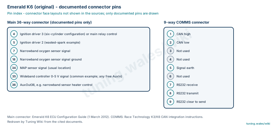
The original Emerald K6 (introduced in 2010) has a 36-way main connector and a 9-way COMMS connector. This page lists only the positions named in Emerald's K6 configuration guide and the COMMS connector; the complete 36-way table from Emerald's K6 part-loom wiring details is given in Emerald K6 and K6+ 36-way connector pinout. The K6 ECU Configuration Guide (manufacturer documentation) uses pin 4 for ignition driver 3 in a six-cylinder configuration or otherwise main relay control, and pin 5 for ignition driver 2 in its wasted-spark example. A narrowband lambda sensor connects to pin 7 with its ground on pin 18; the MAP sensor signal is usually on pin 34; a wideband controller's 0–5 V output is commonly taken to pin 35 (any free auxiliary input can be used); and AuxOut36 serves as an example narrowband heater control.
The 9-way COMMS connector carries CAN high and low on pins 1 and 2, signal earth on pin 5 and RS232 receive, transmit and clear-to-send on pins 7 to 9, according to Race Technology's integration instructions for its data loggers (third-party documentation, graded suspected). Both connectors are drawn as pin indexes because their faces are not shown in the sources. The COMMS assignments come from documentation covering the K3 and K6; check the actual unit and its configuration before wiring.
Sources
- Emerald K6 ECU Configuration Guide Rev 3, Emerald M3D, 1 March 2012. Manufacturer documentation. Accessed 19 November 2026.
- Race Technology: Emerald K3 and K6 CAN; COMMS connector assignments. Third-party integration instructions. Accessed 19 November 2026.
Connector pinout
Original Emerald K6 (introduced 2010). Only pins documented in the sources are listed: seven main 36-way connector positions from the Emerald K6 ECU Configuration Guide (1 March 2012; manufacturer documentation, configuration examples) and the 9-way COMMS connector from Race Technology's K3/K6 CAN integration instructions (third-party, graded suspected). A full K6 main-connector table and the connector face are not given in these sources, so both connectors are drawn as pin indexes. Not to be transferred to the K6+.
View orientation is stated beside each photograph. Unknown functions remain in the pin index.
Main 36-way connector (documented pins only)
View: Pin index; face layout not shown in the source
Select a pin in a photograph or the index to highlight it.
| Pin | Function / cavity | Confidence / source | Notes |
|---|---|---|---|
| Ignition driver 3 (six-cylinder configuration) or main relay control Cavity: Populated |
Confirmed Emerald K6 Configuration Guide 2012 |
||
| Ignition driver 2 (wasted-spark example) Cavity: Populated |
Confirmed Emerald K6 Configuration Guide 2012 |
||
| Narrowband oxygen sensor signal Cavity: Populated |
Confirmed Emerald K6 Configuration Guide 2012 |
||
| Narrowband oxygen sensor signal ground Cavity: Populated |
Confirmed Emerald K6 Configuration Guide 2012 |
||
| MAP sensor signal (usual location) Cavity: Populated |
Confirmed Emerald K6 Configuration Guide 2012 |
||
| Wideband controller 0-5 V signal (common example; any free AuxIn) Cavity: Populated |
Confirmed Emerald K6 Configuration Guide 2012 |
||
| AuxOut36, e.g. narrowband sensor heater control Cavity: Populated |
Confirmed Emerald K6 Configuration Guide 2012 |
9-way COMMS connector
View: Pin index; face layout not shown in the source
Select a pin in a photograph or the index to highlight it.
| Pin | Function / cavity | Confidence / source | Notes |
|---|---|---|---|
| CAN high Cavity: Populated |
Suspected Race Technology K3/K6 CAN instructions |
||
| CAN low Cavity: Populated |
Suspected Race Technology K3/K6 CAN instructions |
||
| Not used Cavity: Unused |
Suspected Race Technology K3/K6 CAN instructions |
||
| Not used Cavity: Unused |
Suspected Race Technology K3/K6 CAN instructions |
||
| Signal earth Cavity: Populated |
Suspected Race Technology K3/K6 CAN instructions |
||
| Not used Cavity: Unused |
Suspected Race Technology K3/K6 CAN instructions |
||
| RS232 receive Cavity: Populated |
Suspected Race Technology K3/K6 CAN instructions |
||
| RS232 transmit Cavity: Populated |
Suspected Race Technology K3/K6 CAN instructions |
||
| RS232 clear to send Cavity: Populated |
Suspected Race Technology K3/K6 CAN instructions |