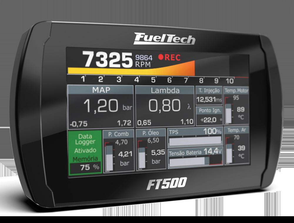
FuelTech FT500 is a PowerFT engine-management unit. PowerFT ECU with eight blue injector and eight grey ignition outputs. Unused grey/yellow outputs can be allocated to injection only with the driver specified in the manual. FuelTech model documentation · FuelTech range comparison.
Identification and software
Record the exact model, serial, harness, firmware and configured outputs; similarly named FT models may use different connectors and functions. Tuning software: FTManager; FT500/500LITE software compatibility is capped at 4.91 per FuelTech. FuelTech software and compatibility.
Wiring and pinout
Use the model-specific manual and the current FuelTech manuals index for connector view, cavity numbering, fuse values, sensor grounds and injector-driver limits. The manufacturer wiring archive contains installation-specific examples; match the exact ECU and harness before wiring. Pin functions depend on the model, hardware and configured output.
See FuelTech engine-management family for other models and company background. FuelTech is based in Brazil and has a US operation in Georgia. Sources reviewed 17 November 2026.
FT500 SFI / FT500LITE SFI ECU connector assignments
The FuelTech FT500 SFI / FT500LITE SFI installation manual, sections 4.1–4.2, specifies these rear-view connector positions. Sensor inputs and blue, gray and yellow outputs can be configured. Verify the ECU revision, wiring view, electrical ratings and grounding before use; the magnetic RPM reference is not a general sensor ground.
24-way connector
| Pin | Function |
|---|---|
| 1 | Gray output #8 |
| 2 | Blue output #6 |
| 3 | White input #7 |
| 4 | Blue output #7 |
| 5 | White input #6 |
| 6 | Blue output #8 |
| 7 | White input #5 |
| 8 | Magnetic RPM sensor reference |
| 9 | White input #4 |
| 10 | Gray output #5 |
| 11 | White input #11 |
| 12 | Gray output #4 |
| 13 | Blue output #3 |
| 14 | Gray output #3 |
| 15 | Cam sync signal input |
| 16 | Gray output #2 |
| 17 | RPM signal input |
| 18 | Gray output #1 |
| 19 | Battery negative input |
| 20 | 5 V output for sensors |
| 21 | 12 V input from main relay |
| 22 | Power ground |
| 23 | Blue output #2 |
| 24 | Blue output #1 |
16-way connector
| Pin | Function |
|---|---|
| 1 | White input #1 |
| 2 | Gray output #6 |
| 3 | White input #10 |
| 4 | Gray output #7 |
| 5 | White input #2 |
| 6 | Blue output #4 |
| 7 | White input #3 |
| 8 | Blue output #5 |
| 9 | Power ground |
| 10 | White input #9 |
| 11 | Power ground |
| 12 | White input #8 |
| 13 | Yellow output #1 |
| 14 | Yellow output #2 |
| 15 | Yellow output #3 |
| 16 | Yellow output #4 |
Do not infer these assignments from earlier FT-series looms: FuelTech documents repurposed wires and pins when upgrading from older models.
Structured pinout
A structured pin index and redrawn connector diagrams for the FT500 and FT500LITE are in FuelTech FT500 and FT500LITE connector pinout.
Not established
The microcontroller used in the FT500 and FT500LITE is not named in FuelTech's published documentation.