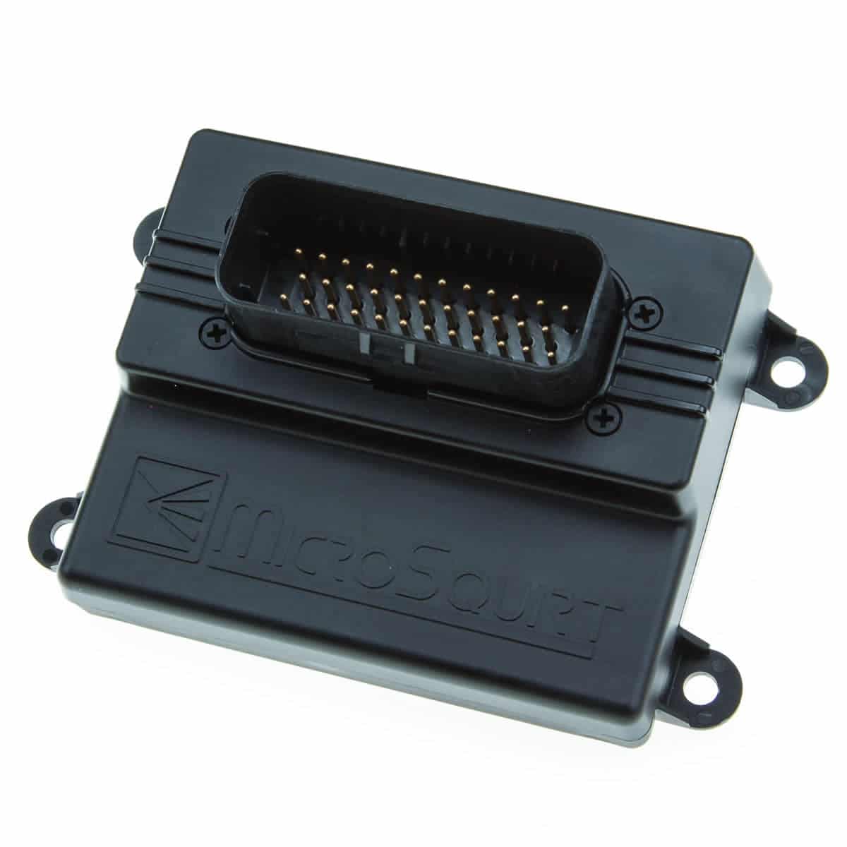
MicroSquirt V3 is a MegaSquirt-family engine-management product. Compact MicroSquirt V3 ECU; its AMPSEAL connector is not pin-compatible with the later MS3Pro Mini despite similar physical appearance. Model source.
Identification and software
Record the ECU label, processor generation, board revision, firmware and installed hardware modifications. Calibration software and firmware must match the hardware. DIYAutoTune software and firmware · Model-specific information.
Wiring and pinout
Use the matching model document and wiring or support reference; the manufacturer manual index distinguishes wire-in and vehicle-specific variants. Check connector orientation, wiring changes, fuse ratings and output configuration before connecting loads; matching cases or software families do not establish identical pin functions.
See the MegaSquirt and MS3Pro family guide. Sources reviewed 17 November 2026.
Engine-control hardware
DIYAutoTune lists two high-impedance injector outputs and two dedicated ignition outputs, plus two general-purpose outputs that can be repurposed as ignition. It has two VR-conditioned inputs and an optoisolated RPM input. Different firmware can instead use the same hardware as a transmission controller or CAN I/O device; identify the firmware before assuming an engine-control installation. MicroSquirt V3 product specification.
35-way AMPSEAL connector
Functions below follow the MicroSquirt V3 wiring guide. The V3 quick-start identifies pins 4 and 21 as VR2+ and VR2−. Do not substitute the earlier hardware's pin 21 ground assignment. See its connector view, electrical limits and related input guidance before wiring; supported assignments can depend on firmware and hardware modifications.
| Pin | Function in guide |
|---|---|
| 1 | 12 Volt Supply |
| 2 | CAN High |
| 3 | CAN Low |
| 4 | VRIN2+ |
| 5 | Spare Input 2 |
| 6 | Flex Fuel |
| 7 | FIDLE |
| 8 | FUEL PUMP |
| 9 | INJECTOR 1 |
| 10 | INJECTOR 2 |
| 11 | IGNITION OUTPUT #2 |
| 12 | IGNITION OUTPUT #1 |
| 13 | SERIAL Rx (pre-wired) |
| 14 | SERIAL Tx (pre-wired) |
| 15 | BOOTLOADER |
| 16 | ACCEL LED |
| 17 | Warm-Up LED |
| 18 | 2ND SENSOR GROUND |
| 19 | SERIAL GROUND (pre-wired) |
| 20 | SENSOR GROUND |
| 21 | VR2IN- |
| 22 | GROUND |
| 23 | GROUND |
| 24 | MAP |
| 25 | CLT |
| 26 | IAT |
| 27 | TPS |
| 28 | Vref |
| 29 | Spare Input 1 |
| 30 | OPTOIN+ |
| 31 | OPTOIN- |
| 32 | VRIN1+ |
| 33 | VRIN1- |
| 34 | O2 |
| 35 | TACH OUTPUT |
Structured pinout
The same 35-way connector, with harness colours and current ratings from the manufacturer's Microsquirt Hardware Manual (MS2/Extra 3.4.x), is tabulated and redrawn as a pin index in MicroSquirt V3 and V2 AMPSEAL connector pinout. The manual names pins 11 and 12 as Spark B and Spark A logic outputs (0.02 A) for external coil drivers, and pins 16 and 17 as spare 3 A relay outputs. Microsquirt Hardware Manual, dated 19 January 2016, accessed 19 November 2026.