Connector pinout
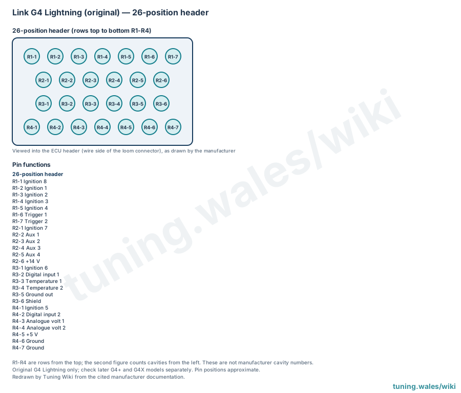
The original (pre-G4+) Link G4 Lightning has a single 26-position header arranged in four rows of 7, 6, 6 and 7 cavities. Link's 2010 G4 wiring and installation manual (manufacturer documentation) gives a function and loom colour for every position. It draws the header viewed into the ECU, which is the wire side of the loom connector, but prints no cavity numbers. Positions are therefore named here by row from the top (R1 to R4) and by count from the left; these names are not manufacturer cavity numbers.
The header carries eight ignition outputs (Ignition 1 to 8), two trigger inputs, four auxiliary outputs, two digital inputs, two temperature inputs and two analogue voltage inputs; no injector drives are listed. Ignition 5 to 8 occupy the positions that carry injector drives on the original G4 Atom header, with the same loom colours. Power and reference connections are +14 V, +5 V, two grounds, a ground out and a shield. The pin index gives each position's loom colour.
The layout applies to the original G4 Lightning only. Later G4+ and G4X models must be checked separately, and the actual unit and loom should be confirmed before wiring. The original G4 Atom header uses the same housing.
Sources
- G4 wiring and installation manual. Link Electrosystems, manufacturer installation manual, 2010; original G4 Lightning header drawing on page 17. Accessed 19 November 2026.
Connector pinout
Link G4 Lightning, original (pre-G4+) generation. Functions and loom colours from Link's G4 wiring and installation manual (2010), page 17, which shows the 26-position header viewed into the ECU (wire side of the loom connector) without cavity numbers. Positions are named by row from the top (R1-R4) and by count from the left; these names are not manufacturer cavity numbers. Does not apply to later G4+ or G4X models.
View orientation is stated beside each photograph. Unknown functions remain in the pin index.
26-position main header
View: Viewed into the ECU header (wire side of the loom connector), as drawn by the manufacturer
Select a pin in a photograph or the index to highlight it.
| Pin | Function / cavity | Confidence / source | Notes |
|---|---|---|---|
| Ignition 8 Cavity: Populated |
Confirmed Link G4 installation manual (2010), p. 17 |
Loom colour Brown/orange. | |
| Ignition 1 Cavity: Populated |
Confirmed Link G4 installation manual (2010), p. 17 |
Loom colour Blue. | |
| Ignition 2 Cavity: Populated |
Confirmed Link G4 installation manual (2010), p. 17 |
Loom colour Blue/brown. | |
| Ignition 3 Cavity: Populated |
Confirmed Link G4 installation manual (2010), p. 17 |
Loom colour Blue/red. | |
| Ignition 4 Cavity: Populated |
Confirmed Link G4 installation manual (2010), p. 17 |
Loom colour Blue/orange. | |
| Trigger 1 Cavity: Populated |
Confirmed Link G4 installation manual (2010), p. 17 |
Loom colour Black. | |
| Trigger 2 Cavity: Populated |
Confirmed Link G4 installation manual (2010), p. 17 |
Loom colour Red. | |
| Ignition 7 Cavity: Populated |
Confirmed Link G4 installation manual (2010), p. 17 |
Loom colour Brown/red. | |
| Aux 1 Cavity: Populated |
Confirmed Link G4 installation manual (2010), p. 17 |
Loom colour Orange/black. | |
| Aux 2 Cavity: Populated |
Confirmed Link G4 installation manual (2010), p. 17 |
Loom colour Orange/brown. | |
| Aux 3 Cavity: Populated |
Confirmed Link G4 installation manual (2010), p. 17 |
Loom colour Orange/red. | |
| Aux 4 Cavity: Populated |
Confirmed Link G4 installation manual (2010), p. 17 |
Loom colour Orange. | |
| +14 V Cavity: Populated |
Confirmed Link G4 installation manual (2010), p. 17 |
Loom colour Red. | |
| Ignition 6 Cavity: Populated |
Confirmed Link G4 installation manual (2010), p. 17 |
Loom colour Brown. | |
| Digital input 1 Cavity: Populated |
Confirmed Link G4 installation manual (2010), p. 17 |
Loom colour Grey/black. | |
| Temperature 1 Cavity: Populated |
Confirmed Link G4 installation manual (2010), p. 17 |
Loom colour Yellow. | |
| Temperature 2 Cavity: Populated |
Confirmed Link G4 installation manual (2010), p. 17 |
Loom colour Yellow/brown. | |
| Ground out Cavity: Populated |
Confirmed Link G4 installation manual (2010), p. 17 |
Loom colour Green. | |
| Shield Cavity: Populated |
Confirmed Link G4 installation manual (2010), p. 17 |
Loom colour Green. | |
| Ignition 5 Cavity: Populated |
Confirmed Link G4 installation manual (2010), p. 17 |
Loom colour Brown/black. | |
| Digital input 2 Cavity: Populated |
Confirmed Link G4 installation manual (2010), p. 17 |
Loom colour Grey/brown. | |
| Analogue volt 1 Cavity: Populated |
Confirmed Link G4 installation manual (2010), p. 17 |
Loom colour Yellow/blue. | |
| Analogue volt 2 Cavity: Populated |
Confirmed Link G4 installation manual (2010), p. 17 |
Loom colour White/brown. | |
| +5 V Cavity: Populated |
Confirmed Link G4 installation manual (2010), p. 17 |
Loom colour Red/blue. | |
| Ground Cavity: Populated |
Confirmed Link G4 installation manual (2010), p. 17 |
Loom colour Black. | |
| Ground Cavity: Populated |
Confirmed Link G4 installation manual (2010), p. 17 |
Loom colour Black. |