Connector pinout
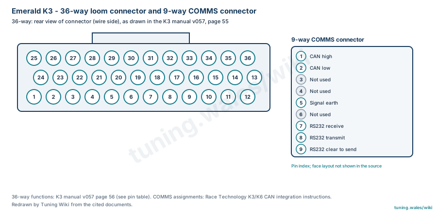
The Emerald K3 has a 36-way loom connector for all engine inputs, outputs and supplies, and a separate 9-way COMMS connector. The Emerald K3 manual v057 gives the 36-way pin-out table on page 56 and draws the connector on page 55 as a rear (wire-side) view: pins 25 to 36 run left to right along the top row, pins 24 to 13 along the offset middle row and pins 1 to 12 along the bottom row. All 36 pins are listed here as manufacturer documentation.
Supplies are the ignition sense input on pin 11 and the +12 V ignition supply on pin 28, with the ECU earth on pin 29 (direct to battery) and the sensor earth on pin 30; sensor supplies are +5 V (pin 9, 100 mA maximum) and +8 V (pin 14). Injector drivers 1 and 2 are on pins 24 and 23, with injector drivers 3 to 6 shared with auxiliary outputs on pins 26, 1, 17 and 21; ignition driver 1 is pin 25, with drivers 2 to 4 shared on pins 5, 4 and 17. The main trigger input is pin 31 with its sensor earth on pin 32, and the cam phase input pin 15. Coolant and air temperature are on pins 33 and 16, throttle position pin 8 and narrowband oxygen pins 7 and 18. Apart from the tacho output (pin 12), all driver outputs are switched earths; the manual specifies high-impedance injectors, or ballast resistors for low-impedance injectors. Slash-separated functions depend on the ECU configuration, and pin 21 is printed in the manual as "Injector driver 6/AuxOut3".
The 9-way COMMS connector carries CAN high and low on pins 1 and 2, signal earth on pin 5 and RS232 receive, transmit and clear-to-send on pins 7 to 9, according to Race Technology's integration instructions for its data loggers (third-party documentation, graded suspected). Its face layout is not shown in that source, so it is drawn as a pin index. These assignments are not established for K6, K6+ or bespoke Emerald units.
Sources
- Emerald K3 Manual v057, Emerald M3D; pages 55 (36-way loom connector drawing) and 56 (ECU pin out table). Manufacturer documentation. Accessed 19 November 2026.
- Race Technology: Emerald K3 and K6 CAN; COMMS connector assignments. Third-party integration instructions. Accessed 19 November 2026.
Connector pinout
Emerald K3 (produced 2007-2010). 36-way loom connector: functions from the Emerald K3 manual v057, page 56, and face from page 55 (rear view, wire side); manufacturer documentation. Slash-separated functions depend on ECU configuration; apart from the tacho output all driver outputs are switched earths. Pin 21 is printed as 'Injector driver 6/AuxOut3' in the manual. The 9-way COMMS connector assignments come from Race Technology's K3/K6 CAN integration instructions (third-party, graded suspected); its face layout is not shown, so it is drawn as a pin index. Not established for K6, K6+ or bespoke units.
View orientation is stated beside each photograph. Unknown functions remain in the pin index.
36-way loom connector
View: Rear view of connector (wire side), as drawn in the manufacturer manual
Select a pin in a photograph or the index to highlight it.
| Pin | Function / cavity | Confidence / source | Notes |
|---|---|---|---|
| Injector driver 4/AuxOut1 Cavity: Populated |
Confirmed Emerald K3 manual v057 p.56 |
Injector driver 4 or user assigned output | |
| IACV2/AuxOut2 Cavity: Populated |
Confirmed Emerald K3 manual v057 p.56 |
IACV stepper motor channel 2 or user assigned outputt | |
| IACV1/IACV-PWM/AuxOut3 Cavity: Populated |
Confirmed Emerald K3 manual v057 p.56 |
IACV stepper motor channel 1, IACV pwm control or user assigned output | |
| Ignition driver 3/Main Relay Control Cavity: Populated |
Confirmed Emerald K3 manual v057 p.56 |
Ignition driver 3 or main relay control output according to ECU configuration | |
| Ignition driver 2/AuxOut5 Cavity: Populated |
Confirmed Emerald K3 manual v057 p.56 |
Ignition driver 2 or user assigned output | |
| Cooling fan relay control Cavity: Populated |
Confirmed Emerald K3 manual v057 p.56 |
Output switches to earth to activate relay & fan | |
| Oxygen sensor signal input Cavity: Populated |
Confirmed Emerald K3 manual v057 p.56 |
0-1v input from narrow band sensor | |
| Throttle pot signal input Cavity: Populated |
Confirmed Emerald K3 manual v057 p.56 |
0-5v input from throttle position sensor | |
| +5v sensor supply Cavity: Populated |
Confirmed Emerald K3 manual v057 p.56 |
5v output, 100mA max supply for sensors such as TPS, MAP, etc | |
| AuxIn10 Cavity: Populated |
Confirmed Emerald K3 manual v057 p.56 |
User assigned 0-5v input. An internally switched pull-up resistor can be enabled on this input. | |
| Ignition sense input Cavity: Populated |
Confirmed Emerald K3 manual v057 p.56 |
+12v supply via ignition switch | |
| Tacho output signal Cavity: Populated |
Confirmed Emerald K3 manual v057 p.56 |
0-12v pulsed output | |
| Immobilisor/EGT digital input Cavity: Populated |
Confirmed Emerald K3 manual v057 p.56 |
Digital input from a Lucas 5AS immobilisor or VAG EGT sensor interface | |
| +8v sensor supply Cavity: Populated |
Confirmed Emerald K3 manual v057 p.56 |
+8v supply for external sensors | |
| Cam phase or custom input Cavity: Populated |
Confirmed Emerald K3 manual v057 p.56 |
Cam sensor input (if required) | |
| Air temperature signal input Cavity: Populated |
Confirmed Emerald K3 manual v057 p.56 |
NTC temperature sensor input | |
| Injector driver 5/Ignition driver 4/AuxOut17 Cavity: Populated |
Confirmed Emerald K3 manual v057 p.56 |
Injector driver 5, Ignition driver 4 or user assigned output according to ECU configuration | |
| Oxygen sensor signal earth Cavity: Populated |
Confirmed Emerald K3 manual v057 p.56 |
||
| Shift-light driver/AuxOut19 Cavity: Populated |
Confirmed Emerald K3 manual v057 p.56 |
Shift-light output (switched earth) or user assigned output according to ECU configuration | |
| Fuel pump relay driver Cavity: Populated |
Confirmed Emerald K3 manual v057 p.56 |
Switched earth | |
| Injector driver 6/AuxOut3 Cavity: Populated |
Confirmed Emerald K3 manual v057 p.56 |
Injector driver 6 or user assigned output | |
| IACV3/AuxOut22 Cavity: Populated |
Confirmed Emerald K3 manual v057 p.56 |
IACV stepper motor control or user assigned output | |
| Injector driver 2 Cavity: Populated |
Confirmed Emerald K3 manual v057 p.56 |
||
| Injector driver 1 Cavity: Populated |
Confirmed Emerald K3 manual v057 p.56 |
||
| Ignition driver 1 Cavity: Populated |
Confirmed Emerald K3 manual v057 p.56 |
||
| Injector driver 3/AuxOut26 Cavity: Populated |
Confirmed Emerald K3 manual v057 p.56 |
Injector driver 3 or user assigned output | |
| IACV 4/AuxOut27 Cavity: Populated |
Confirmed Emerald K3 manual v057 p.56 |
IACV stepper motor control or user assigned output | |
| +12v Ignition supply Cavity: Populated |
Confirmed Emerald K3 manual v057 p.56 |
Supply from main relay or common with pin 11 | |
| ECU earth Cavity: Populated |
Confirmed Emerald K3 manual v057 p.56 |
Good earth (direct to battery) | |
| Sensor earth Cavity: Populated |
Confirmed Emerald K3 manual v057 p.56 |
Common earth for air, coolant & throttle sensors | |
| Main trigger signal input Cavity: Populated |
Confirmed Emerald K3 manual v057 p.56 |
Crank sensor or digital distributor input signal | |
| Main trigger sensor earth Cavity: Populated |
Confirmed Emerald K3 manual v057 p.56 |
Earth return for main/cam trigger sensors | |
| Coolant temp signal input Cavity: Populated |
Confirmed Emerald K3 manual v057 p.56 |
NTC temperature sensor input | |
| AuxIn34 Cavity: Populated |
Confirmed Emerald K3 manual v057 p.56 |
User assigned 0–5v input | |
| AuxIn35 Cavity: Populated |
Confirmed Emerald K3 manual v057 p.56 |
User assigned 0-5v input. An internally switched pull-up resistor can be enabled on this input for temperature sensors. | |
| AuxIn36/AuxOut36 Cavity: Populated |
Confirmed Emerald K3 manual v057 p.56 |
User configurable input or output pin |
9-way COMMS connector
View: Pin index; face layout not shown in the source
Select a pin in a photograph or the index to highlight it.
| Pin | Function / cavity | Confidence / source | Notes |
|---|---|---|---|
| CAN high Cavity: Populated |
Suspected Race Technology K3/K6 CAN instructions |
||
| CAN low Cavity: Populated |
Suspected Race Technology K3/K6 CAN instructions |
||
| Not used Cavity: Unused |
Suspected Race Technology K3/K6 CAN instructions |
||
| Not used Cavity: Unused |
Suspected Race Technology K3/K6 CAN instructions |
||
| Signal earth Cavity: Populated |
Suspected Race Technology K3/K6 CAN instructions |
||
| Not used Cavity: Unused |
Suspected Race Technology K3/K6 CAN instructions |
||
| RS232 receive Cavity: Populated |
Suspected Race Technology K3/K6 CAN instructions |
||
| RS232 transmit Cavity: Populated |
Suspected Race Technology K3/K6 CAN instructions |
||
| RS232 clear to send Cavity: Populated |
Suspected Race Technology K3/K6 CAN instructions |