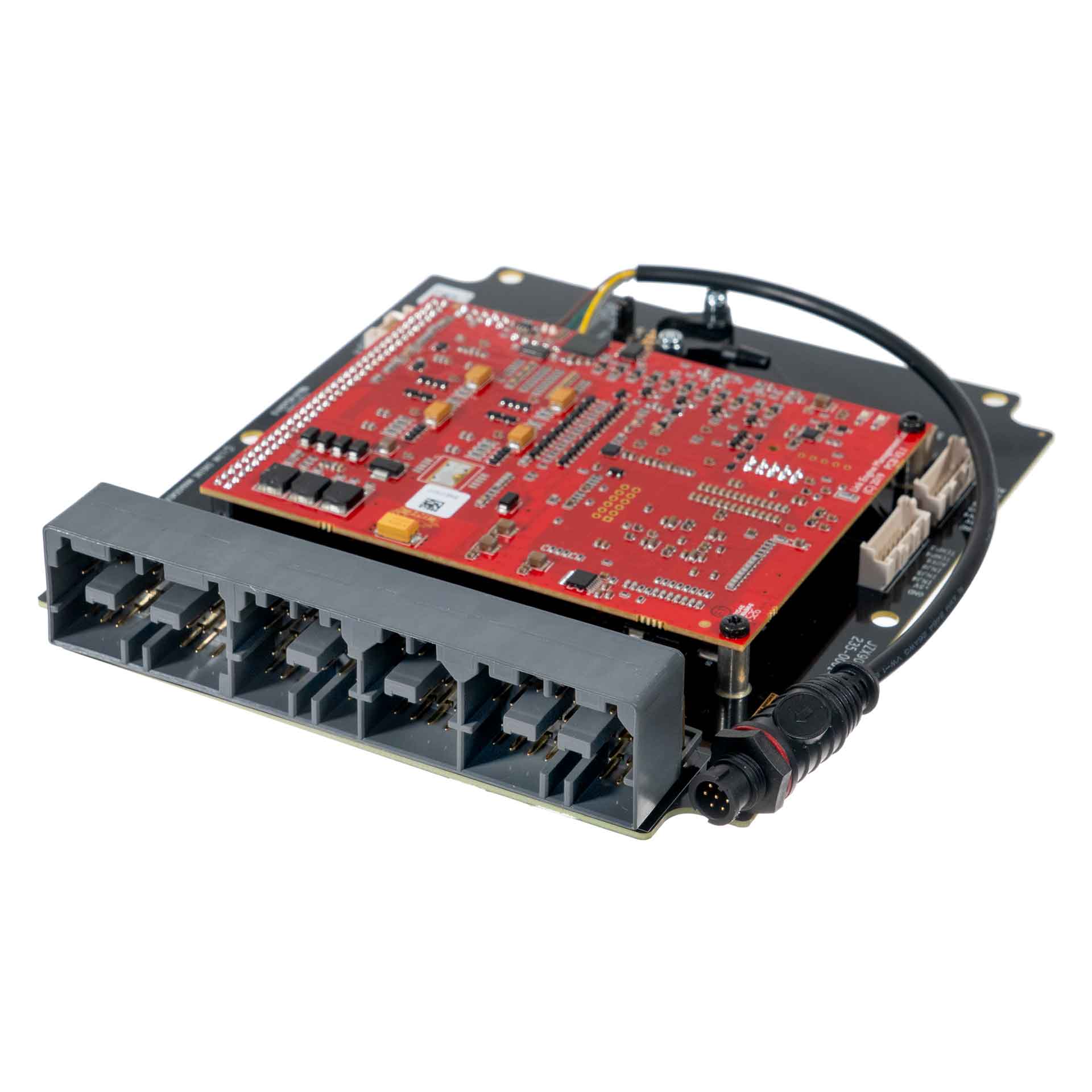
Link G4X JZX90X is a vehicle-specific programmable plug-in ECU for the Toyota JZX90 application listed in Link's model-specific manuals index. It is an application board rather than a universal wire-in ECU. Check the exact vehicle, market, engine, original ECU and board part number against the manufacturer's JZX90X installation manual.
Identification and installation
Record the Link model label and revision, donor factory ECU connector and car's engine and year. Plug-in boards connect to particular factory-harness layouts; the family or vehicle name alone does not establish every model-year or transmission combination. The manufacturer manual gives the supported application and any installation or configuration notes for this board.
G4X plug-in platforms offer configurable fuel and ignition control but available channels and features depend on the original header and board. The G4X plug-in general specifications are conditional on the particular application and do not mean every input is brought out to the factory harness.
Processor and hardware
Link's G4X plug-in specifications describe a 150 MHz "specialised engine management microprocessor" with 32-bit floating-point calculation, 12-bit ADC resolution, 4 Gb non-volatile flash, 512 MB of data logging and two CAN buses (vendor specification). The processor part number is not published by Link.
Engine application
Link's installation manual is written for the Toyota JZX90 and supports sequential injection using Injectors 4–6 on the expansion connector. Retailer listings name this ECU (part number 235-4000) for the 1JZ-GTE without VVT-i in the JZX90 Chaser, Cresta and Mark II (seen in search summary; not confirmed from Link's own page).
Pinout and tuning
The JZX90X installation manual is the model-specific source for board pinouts, expansion connections, electrical cautions and startup configuration. Use its connector orientation and the exact board version; do not copy a wire-in ECU pinout onto a factory harness. PCLink and manual downloads; Link manufacturer overview.
A structured, redrawn version of the schedules below, with the 100-pin main header face, is in Link G4X JZX90X connector pinout.
Manufacturer connector schedules
From Link's JZX90 installation manual. Pinouts are viewed looking into the ECU from the wire side. A dash reproduces an unspecified source field; nc is Link's label. Confirm the exact board revision and vehicle harness before use.
Injector drive 8 controls the main relay through dedicated high-side hardware. Link reports that on V1.4 and earlier boards Aux 6 and Aux 7 idle-stepper wiring is reversed. Follow the source guide for the affected revision.
Factory main header
| Factory pin | Link ECU channel | Factory function |
|---|---|---|
| 1 | Injector 1 | Injection |
| 65 | nc | — |
| 2 | Injector 2 | Injection |
| 66 | nc | — |
| 3 | Injector 3 | Injection |
| 67 | nc | — |
| 4 | Aux 1 | Purge |
| 68 | Ground | — |
| 5 | nc | — |
| 69 | nc | — |
| 6 | Knock 1 | Knock |
| 70 | nc | — |
| 7 | Knock 2 | Knock |
| 71 | nc | — |
| 8 | Injector 7 (Aux) | NB O2 Heater |
| 72 | nc | — |
| 9 | nc | — |
| 73 | nc | — |
| 10 | nc | — |
| 74 | nc | — |
| 11 | Ignition 2 | Ignition |
| 75 | nc | — |
| 12 | Ignition 3 | Ignition |
| 76 | Ignition 7 | AC Clutch |
| 13 | nc | — |
| 77 | nc | — |
| 14 | DI 1 | Start Switch |
| 78 | nc | — |
| 15 | nc | — |
| 79 | nc | — |
| 16 | nc | — |
| 80 | nc | — |
| 17 | Ignition 4 | Ignition |
| 81 | nc | — |
| 18 | nc | — |
| 82 | DI 3 | Gearbox Speed |
| 19 | Ignition 1 | Ignition |
| 83 | nc | — |
| 20 | Aux 5 | ISC Stepper |
| 84 | nc | — |
| 21 | Aux 6 | ISC Stepper |
| 85 | DI 5 | Ignition Switch (Controls Main Relay Output) |
| 22 | Aux 7 | ISC Stepper |
| 86 | nc | — |
| 23 | Aux 8 | ISC Stepper |
| 87 | DI 6 | AC Request |
| 24 | nc | — |
| 88 | nc | — |
| 25 | nc | — |
| 89 | nc | — |
| 26 | nc | — |
| 90 | nc | — |
| 27 | Ground (Signal) | — |
| 91 | nc | — |
| 28 | Ground (Signal) | — |
| 92 | nc | — |
| 29 | nc | — |
| 93 | +12V Hot feed | Used for Hold Power and Flywheeling |
| 30 | nc | — |
| 94 | nc | — |
| 31 | Ignition 5 | Ignition |
| 95 | nc | — |
| 32 | Ignition 6 | Ignition |
| 96 | nc | — |
| 33 | Ground | — |
| 97 | nc | — |
| 34 | nc | — |
| 98 | nc | — |
| 35 | Ground (Triggers) | — |
| 99 | +14V | ECU Power |
| 36 | Trig 1 | Trigger 1 |
| 100 | +14V | ECU Power |
| 37 | nc | — |
| 38 | nc | — |
| 39 | nc | — |
| 40 | +5V Out | — |
| 41 | Ground (Triggers) | — |
| 42 | Trig 2 | Trigger 2 |
| 43 | nc | — |
| 44 | An Volt 1 via jumper | Factory MAP Sensor |
| 45 | An Volt 2 | TPS |
| 46 | Ground (Triggers) | — |
| 47 | DI 2 | Another CAM Sensor |
| 48 | nc | — |
| 49 | An Temp 2 | IAT |
| 50 | An Volt 3 | NB O2 Sensor |
| 51 | VTA2 | Buffered copy sent out pin 64 |
| 52 | Ground | — |
| 53 | nc | — |
| 54 | An Temp 1 | ECT |
| 55 | nc | — |
| 56 | nc | — |
| 57 | Aux 2 | FP Speed (PWM) |
| 58 | Aux 3 | CE Light |
| 59 | Main Relay Output | Pull high to activate |
| 60 | Trig 1 | Trigger 1 Output |
| 61 | Buffered Copy of An Volt 2 | — |
| 62 | DI 4 | Timing Retard Request |
| 63 | nc | — |
| 64 | Buffered Copy of VTA2 (Pin 51) | — |
Expansion connector
| Position | Link ECU channel | Function |
|---|---|---|
| Expansion 1 | Ground (Signal) | — |
| Expansion 2 | +5V Out | — |
| Expansion 3 | Injector 4 | — |
| Expansion 4 | Injector 5 | — |
| Expansion 5 | Injector 6 | — |
| Expansion 6 | Aux 4 | — |
| Expansion 7 | An Temp 4 | — |
| Expansion 8 | An Temp 3 | — |
| Expansion 9 | Ground (Signal) | — |
| Expansion 10 | +5V Out | — |
| Expansion 11 | DI 7 | — |
| Expansion 12 | DI 8 | — |
| Expansion 13 | DI 9 | — |
| Expansion 14 | An Volt 8 | — |
| Expansion 15 | An Volt 9 | — |
| Expansion 16 | An Volt 10 | — |
Electronic throttle connector
| Position | Link ECU channel | Function |
|---|---|---|
| E-Throttle plug 1 | Ground (Signal) | — |
| E-Throttle plug 2 | +5V Out | — |
| E-Throttle plug 3 | An Volt 4 | — |
| E-Throttle plug 4 | An Volt 5 | — |
| E-Throttle plug 5 | An Volt 6 | — |
| E-Throttle plug 6 | An Volt 7 | — |
| E-Throttle plug 7 | Aux 10 | — |
| E-Throttle plug 8 | Aux 9 | — |
Other documented connections
| Position | Link ECU channel | Function |
|---|---|---|
| Main Relay Control | Injector 8 | ECU Hold Power |
| On Board MAP | An Volt 1 via jumper | MAP |
| E-Throttle Relay | Aux 16 | (Only needed if converting to E-Throttle) |
CAN 1 and 2 four-pin connector
| Pin | Function | Wire colour |
|---|---|---|
| 1 | GND | Black |
| 2 | CAN L | Green |
| 3 | CAN H | White |
| 4 | +14V | Red |