Tuning Wiki

This is a historical revision. Read the current page or return to its history.

Page organisation in this revision
Page type
Technical article
Subject
Engine ECU
Parent
MegaSquirt-III
Applies to
MegaSquirt-III
Tool groups
None
Manufacturers
MegaSquirt

Changes from revision 1 to revision 1

Removed text is struck through; added text is highlighted.

The MegaSquirt-3 in its MS3X/V3.57 form (an MS3 card and the MS3X expansion card on the surface-mount V3.57 mainboard) has two 37-pin DB37 connectors: the main connector, shared in layout with the earlier V3.0 board, and the MS3X expansion connector that carries the sequential injection, logic ignition and auxiliary input/output pins. The tables are taken from the MS3X/V3.57 hardware manual for firmware MS3 1.5.x (manufacturer documentation).

Main connector (DB37)

Grounds: 1 (crank sensor ground), 2 (crank sensor shield), 7 (sensor ground), 8 to 14 (spare grounds), 15 to 19 (power grounds); all joined internally.Power: 28 main +12 V feed; 26 5 V supply for the throttle position sensor.Inputs: 20 air temperature, 21 coolant temperature, 22 throttle position, 23 oxygen sensor, 24 crank (tach).Outputs: 32/33 injector bank 1 and 34/35 injector bank 2 (7 A), 30 idle valve (3 A), 37 fuel pump relay (3 A).Optional (internal configuration): 3 and 4 CAN communications (SPR1/SPR2), 5 and 6 spare (SPR3/SPR4), 25, 27, 29 and 31 stepper idle, 36 high-current ignition.

MS3X expansion connector (DB37)

Injectors A to H (5 A each): A 19, B 16, C 13, D 10, E 7, F 4, G 1, H 20.Logic ignition outputs Spark A to H (0-5 V, for external coil drivers or smart coils): A 14, B 33, C 15, D 34, E 35, F 36, G 18, H 37.Grounds: 2, 3, 8, 12 and 17 (power grounds).Inputs: 32 cam (tach), 5 flex fuel, 21 spare 0-5 V analogue, 22 EGO2, 23 external MAP, 11 launch, 28 table switch and 30 datalog (ground-switch inputs), 29 nitrous (+12 V switch input), 31 PT4 (0/5 V input or output).Mid-current outputs (3 A): 6 boost, 9 idle, 24 nitrous 1, 25 nitrous 2, 26 tacho, 27 VVT.

MS3 built on a V3.0 board, or without the MS3X card, has only the main connector. The diagram uses standard D-sub numbering (pins 1 to 19 in the wide row, 20 to 37 in the narrow row); the viewing side is not verified.

Sources

MS3X/V3.57 Hardware Manual, MS3 1.5.x, dated 1 August 2018; main plug and MS3X plug tables (section 3.3). Manufacturer documentation. Accessed 19 November 2026.

Diagram redrawn by Tuning Wiki from the MS3X/V3.57 Hardware Manual.

Rendered revisions

Open each version to inspect formatting, tables and photographs.

Revision 1: MegaSquirt-3 MS3X/V3.57 connector pinout

The MegaSquirt-3 in its MS3X/V3.57 form (an MS3 card and the MS3X expansion card on the surface-mount V3.57 mainboard) has two 37-pin DB37 connectors: the main connector, shared in layout with the earlier V3.0 board, and the MS3X expansion connector that carries the sequential injection, logic ignition and auxiliary input/output pins. The tables are taken from the MS3X/V3.57 hardware manual for firmware MS3 1.5.x (manufacturer documentation).

Main connector (DB37)

  • Grounds: 1 (crank sensor ground), 2 (crank sensor shield), 7 (sensor ground), 8 to 14 (spare grounds), 15 to 19 (power grounds); all joined internally.
  • Power: 28 main +12 V feed; 26 5 V supply for the throttle position sensor.
  • Inputs: 20 air temperature, 21 coolant temperature, 22 throttle position, 23 oxygen sensor, 24 crank (tach).
  • Outputs: 32/33 injector bank 1 and 34/35 injector bank 2 (7 A), 30 idle valve (3 A), 37 fuel pump relay (3 A).
  • Optional (internal configuration): 3 and 4 CAN communications (SPR1/SPR2), 5 and 6 spare (SPR3/SPR4), 25, 27, 29 and 31 stepper idle, 36 high-current ignition.

MS3X expansion connector (DB37)

  • Injectors A to H (5 A each): A 19, B 16, C 13, D 10, E 7, F 4, G 1, H 20.
  • Logic ignition outputs Spark A to H (0-5 V, for external coil drivers or smart coils): A 14, B 33, C 15, D 34, E 35, F 36, G 18, H 37.
  • Grounds: 2, 3, 8, 12 and 17 (power grounds).
  • Inputs: 32 cam (tach), 5 flex fuel, 21 spare 0-5 V analogue, 22 EGO2, 23 external MAP, 11 launch, 28 table switch and 30 datalog (ground-switch inputs), 29 nitrous (+12 V switch input), 31 PT4 (0/5 V input or output).
  • Mid-current outputs (3 A): 6 boost, 9 idle, 24 nitrous 1, 25 nitrous 2, 26 tacho, 27 VVT.

MS3 built on a V3.0 board, or without the MS3X card, has only the main connector. The diagram uses standard D-sub numbering (pins 1 to 19 in the wide row, 20 to 37 in the narrow row); the viewing side is not verified.

Sources

Diagram redrawn by Tuning Wiki from the MS3X/V3.57 Hardware Manual.

Connector pinout

Applicability

MegaSquirt-3 with MS3X expansion on the V3.57 mainboard (MS3X/V3.57), firmware MS3 1.5.x, per the MS3X/V3.57 hardware manual (manufacturer documentation). Two 37-pin DB37 connectors: the main connector and the MS3X expansion connector. Functions in brackets in the manual (CAN on SPR1/SPR2, stepper idle on 25/27/29/31, high-current ignition on 36) depend on internal configuration. All ground pins are joined internally. MS3 on a V3.0 board or without MS3X has only the main connector. Faces drawn with standard D-sub numbering; viewing side not verified.

View orientation is stated beside each photograph. Unknown functions remain in the pin index.

Main connector (DB37, 37 pins)

Redrawn connector face
View: Standard D-sub numbering (pins 1-19 wide row, 20-37 narrow row); viewing side not verified
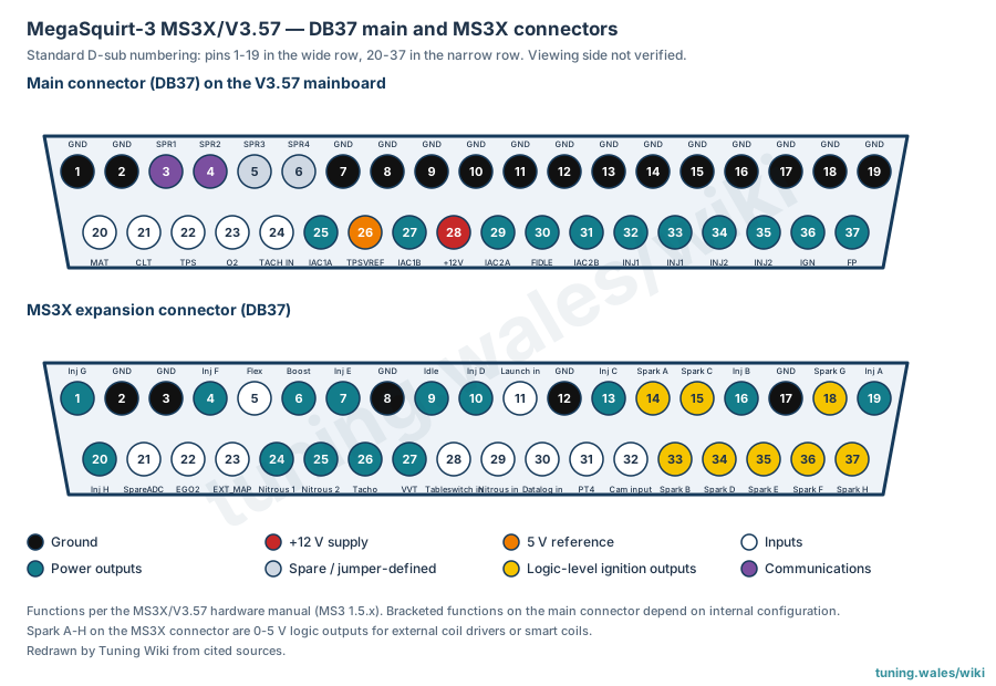
Main connector (DB37, 37 pins) — Redrawn connector face. Standard D-sub numbering (pins 1-19 wide row, 20-37 narrow row); viewing side not verified

Select a pin in a photograph or the index to highlight it.

Main connector (DB37, 37 pins) — complete pin index
PinFunction / cavityConfidence / sourceNotes
Ground (crank sensor ground)
Cavity: Populated
Confirmed

MS3X/V3.57 Hardware Manual, pin tables

Name GND; DIYAutoTune harness colour Black
Ground (crank sensor shield)
Cavity: Populated
Confirmed

MS3X/V3.57 Hardware Manual, pin tables

Name GND
Spare 1 (CAN communications, optional)
Cavity: Populated
Confirmed

MS3X/V3.57 Hardware Manual, pin tables

Name SPR1; DIYAutoTune harness colour Tan
Spare 2 (CAN communications, optional)
Cavity: Populated
Confirmed

MS3X/V3.57 Hardware Manual, pin tables

Name SPR2; DIYAutoTune harness colour Tan/Red
Spare 3
Cavity: Populated
Confirmed

MS3X/V3.57 Hardware Manual, pin tables

Name SPR3; DIYAutoTune harness colour Tan/Green
Spare 4
Cavity: Populated
Confirmed

MS3X/V3.57 Hardware Manual, pin tables

Name SPR4; DIYAutoTune harness colour Tan/Orange
Ground (sensor ground)
Cavity: Populated
Confirmed

MS3X/V3.57 Hardware Manual, pin tables

Name GND; DIYAutoTune harness colour Black/White
Ground (spare)
Cavity: Populated
Confirmed

MS3X/V3.57 Hardware Manual, pin tables

Name GND
Ground (spare)
Cavity: Populated
Confirmed

MS3X/V3.57 Hardware Manual, pin tables

Name GND
Ground (spare)
Cavity: Populated
Confirmed

MS3X/V3.57 Hardware Manual, pin tables

Name GND
Ground (spare)
Cavity: Populated
Confirmed

MS3X/V3.57 Hardware Manual, pin tables

Name GND
Ground (spare)
Cavity: Populated
Confirmed

MS3X/V3.57 Hardware Manual, pin tables

Name GND
Ground (spare)
Cavity: Populated
Confirmed

MS3X/V3.57 Hardware Manual, pin tables

Name GND
Ground (spare)
Cavity: Populated
Confirmed

MS3X/V3.57 Hardware Manual, pin tables

Name GND
Ground (power ground)
Cavity: Populated
Confirmed

MS3X/V3.57 Hardware Manual, pin tables

Name GND; DIYAutoTune harness colour Black
Ground (power ground)
Cavity: Populated
Confirmed

MS3X/V3.57 Hardware Manual, pin tables

Name GND; DIYAutoTune harness colour Black
Ground (power ground)
Cavity: Populated
Confirmed

MS3X/V3.57 Hardware Manual, pin tables

Name GND; DIYAutoTune harness colour Black
Ground (power ground)
Cavity: Populated
Confirmed

MS3X/V3.57 Hardware Manual, pin tables

Name GND; DIYAutoTune harness colour Black
Ground (power ground)
Cavity: Populated
Confirmed

MS3X/V3.57 Hardware Manual, pin tables

Name GND; DIYAutoTune harness colour Black
Manifold air temperature sensor input
Cavity: Populated
Confirmed

MS3X/V3.57 Hardware Manual, pin tables

Name MAT; DIYAutoTune harness colour Orange
Coolant temperature sensor input
Cavity: Populated
Confirmed

MS3X/V3.57 Hardware Manual, pin tables

Name CLT; DIYAutoTune harness colour Yellow
Throttle position sensor input
Cavity: Populated
Confirmed

MS3X/V3.57 Hardware Manual, pin tables

Name TPS; DIYAutoTune harness colour Light Blue
Oxygen (lambda) sensor input
Cavity: Populated
Confirmed

MS3X/V3.57 Hardware Manual, pin tables

Name O2; DIYAutoTune harness colour Pink
Crank (tach) input
Cavity: Populated
Confirmed

MS3X/V3.57 Hardware Manual, pin tables

Name TACH IN; DIYAutoTune harness colour White, shielded
Stepper idle valve 1A (optional)
Cavity: Populated
Confirmed

MS3X/V3.57 Hardware Manual, pin tables

Name IAC1A; DIYAutoTune harness colour Blue/White; max 0.5 A
5 V supply for TPS
Cavity: Populated
Confirmed

MS3X/V3.57 Hardware Manual, pin tables

Name TPSVREF; DIYAutoTune harness colour Gray; max 0.1 A
Stepper idle valve 1B (optional)
Cavity: Populated
Confirmed

MS3X/V3.57 Hardware Manual, pin tables

Name IAC1B; DIYAutoTune harness colour Blue/Red; max 0.5 A
Main +12 V power feed
Cavity: Populated
Confirmed

MS3X/V3.57 Hardware Manual, pin tables

Name +12V; DIYAutoTune harness colour Red; max < 1 A
Stepper idle valve 2A (optional)
Cavity: Populated
Confirmed

MS3X/V3.57 Hardware Manual, pin tables

Name IAC2A; DIYAutoTune harness colour Green/White; max 0.5 A
Idle valve output
Cavity: Populated
Confirmed

MS3X/V3.57 Hardware Manual, pin tables

Name FIDLE; DIYAutoTune harness colour Light Green; max 3 A
Stepper idle valve 2B (optional)
Cavity: Populated
Confirmed

MS3X/V3.57 Hardware Manual, pin tables

Name IAC2B; DIYAutoTune harness colour Green/Red; max 0.5 A
Injector bank 1 output
Cavity: Populated
Confirmed

MS3X/V3.57 Hardware Manual, pin tables

Name INJ1; DIYAutoTune harness colour Blue; max 7 A
Injector bank 1 output
Cavity: Populated
Confirmed

MS3X/V3.57 Hardware Manual, pin tables

Name INJ1; DIYAutoTune harness colour Blue; max 7 A
Injector bank 2 output
Cavity: Populated
Confirmed

MS3X/V3.57 Hardware Manual, pin tables

Name INJ2; DIYAutoTune harness colour Green; max 7 A
Injector bank 2 output
Cavity: Populated
Confirmed

MS3X/V3.57 Hardware Manual, pin tables

Name INJ2; DIYAutoTune harness colour Green; max 7 A
High-current ignition output (optional)
Cavity: Populated
Confirmed

MS3X/V3.57 Hardware Manual, pin tables

Name IGN; DIYAutoTune harness colour Brown; max 7 A
Fuel pump relay output
Cavity: Populated
Confirmed

MS3X/V3.57 Hardware Manual, pin tables

Name FP; DIYAutoTune harness colour Violet; max 3 A

MS3X connector (DB37, 37 pins)

Redrawn connector face
View: Standard D-sub numbering (pins 1-19 wide row, 20-37 narrow row); viewing side not verified
MS3X connector (DB37, 37 pins) — Redrawn connector face. Standard D-sub numbering (pins 1-19 wide row, 20-37 narrow row); viewing side not verified

Select a pin in a photograph or the index to highlight it.

MS3X connector (DB37, 37 pins) — complete pin index
PinFunction / cavityConfidence / sourceNotes
Injector G output
Cavity: Populated
Confirmed

MS3X/V3.57 Hardware Manual, pin tables

Name Inj G; DIYAutoTune harness colour White/Dark Blue; max 5 A
Ground (power ground)
Cavity: Populated
Confirmed

MS3X/V3.57 Hardware Manual, pin tables

Name GND; DIYAutoTune harness colour Black
Ground (power ground)
Cavity: Populated
Confirmed

MS3X/V3.57 Hardware Manual, pin tables

Name GND; DIYAutoTune harness colour Black
Injector F output
Cavity: Populated
Confirmed

MS3X/V3.57 Hardware Manual, pin tables

Name Inj F; DIYAutoTune harness colour White/Dark Green; max 5 A
Flex fuel sensor input
Cavity: Populated
Confirmed

MS3X/V3.57 Hardware Manual, pin tables

Name Flex; DIYAutoTune harness colour Orange
Mid-current output (boost)
Cavity: Populated
Confirmed

MS3X/V3.57 Hardware Manual, pin tables

Name Boost; DIYAutoTune harness colour Light Green/Red; max 3 A
Injector E output
Cavity: Populated
Confirmed

MS3X/V3.57 Hardware Manual, pin tables

Name Inj E; DIYAutoTune harness colour White/Red; max 5 A
Ground (power ground)
Cavity: Populated
Confirmed

MS3X/V3.57 Hardware Manual, pin tables

Name GND; DIYAutoTune harness colour Black
Mid-current output (idle)
Cavity: Populated
Confirmed

MS3X/V3.57 Hardware Manual, pin tables

Name Idle; DIYAutoTune harness colour Light Green/Pink; max 3 A
Injector D output
Cavity: Populated
Confirmed

MS3X/V3.57 Hardware Manual, pin tables

Name Inj D; DIYAutoTune harness colour White/Pink; max 5 A
Ground-switch input (launch)
Cavity: Populated
Confirmed

MS3X/V3.57 Hardware Manual, pin tables

Name Launch in; DIYAutoTune harness colour Gray/Red
Ground (power ground)
Cavity: Populated
Confirmed

MS3X/V3.57 Hardware Manual, pin tables

Name GND; DIYAutoTune harness colour Black
Injector C output
Cavity: Populated
Confirmed

MS3X/V3.57 Hardware Manual, pin tables

Name Inj C; DIYAutoTune harness colour White/Light Green; max 5 A
0-5 V logic spark A output
Cavity: Populated
Confirmed

MS3X/V3.57 Hardware Manual, pin tables

Name Spark A; DIYAutoTune harness colour Yellow; max 0.03 A
0-5 V logic spark C output
Cavity: Populated
Confirmed

MS3X/V3.57 Hardware Manual, pin tables

Name Spark C; DIYAutoTune harness colour Yellow/Light Green; max 0.03 A
Injector B output
Cavity: Populated
Confirmed

MS3X/V3.57 Hardware Manual, pin tables

Name Inj B; DIYAutoTune harness colour White/Orange; max 5 A
Ground (power ground)
Cavity: Populated
Confirmed

MS3X/V3.57 Hardware Manual, pin tables

Name GND; DIYAutoTune harness colour Black
0-5 V logic spark G output
Cavity: Populated
Confirmed

MS3X/V3.57 Hardware Manual, pin tables

Name Spark G; DIYAutoTune harness colour Yellow/Dark Blue; max 0.03 A
Injector A output
Cavity: Populated
Confirmed

MS3X/V3.57 Hardware Manual, pin tables

Name Inj A; DIYAutoTune harness colour White; max 5 A
Injector H output
Cavity: Populated
Confirmed

MS3X/V3.57 Hardware Manual, pin tables

Name Inj H; DIYAutoTune harness colour White/Purple; max 5 A
0-5 V analogue input (spare ADC)
Cavity: Populated
Confirmed

MS3X/V3.57 Hardware Manual, pin tables

Name SpareADC; DIYAutoTune harness colour Light Blue
0-5 V analogue input (EGO2)
Cavity: Populated
Confirmed

MS3X/V3.57 Hardware Manual, pin tables

Name EGO2; DIYAutoTune harness colour Light Blue/Dark Blue
0-5 V analogue input (external MAP)
Cavity: Populated
Confirmed

MS3X/V3.57 Hardware Manual, pin tables

Name EXT_MAP; DIYAutoTune harness colour Light Blue/Red
Mid-current output (nitrous 1)
Cavity: Populated
Confirmed

MS3X/V3.57 Hardware Manual, pin tables

Name Nitrous 1; DIYAutoTune harness colour Light Green; max 3 A
Mid-current output (nitrous 2)
Cavity: Populated
Confirmed

MS3X/V3.57 Hardware Manual, pin tables

Name Nitrous 2; DIYAutoTune harness colour Light Green/Dark Blue; max 3 A
Mid-current output (tacho)
Cavity: Populated
Confirmed

MS3X/V3.57 Hardware Manual, pin tables

Name Tacho; DIYAutoTune harness colour Light Green/Orange; max 3 A
Mid-current output (VVT)
Cavity: Populated
Confirmed

MS3X/V3.57 Hardware Manual, pin tables

Name VVT; DIYAutoTune harness colour Light Green/Dark Green; max 3 A
Ground-switch input (table switch)
Cavity: Populated
Confirmed

MS3X/V3.57 Hardware Manual, pin tables

Name Tableswitch in; DIYAutoTune harness colour Gray/Purple
+12 V switch input (nitrous)
Cavity: Populated
Confirmed

MS3X/V3.57 Hardware Manual, pin tables

Name Nitrous in; DIYAutoTune harness colour Gray/Dark Blue
Ground-switch input (datalog)
Cavity: Populated
Confirmed

MS3X/V3.57 Hardware Manual, pin tables

Name Datalog in; DIYAutoTune harness colour Gray
0/5 V input or output
Cavity: Populated
Confirmed

MS3X/V3.57 Hardware Manual, pin tables

Name PT4; DIYAutoTune harness colour Purple; max 0.02 A
Cam (tach) input
Cavity: Populated
Confirmed

MS3X/V3.57 Hardware Manual, pin tables

Name Cam input; DIYAutoTune harness colour Dark Green
0-5 V logic spark B output
Cavity: Populated
Confirmed

MS3X/V3.57 Hardware Manual, pin tables

Name Spark B; DIYAutoTune harness colour Yellow/Orange; max 0.03 A
0-5 V logic spark D output
Cavity: Populated
Confirmed

MS3X/V3.57 Hardware Manual, pin tables

Name Spark D; DIYAutoTune harness colour Yellow/Pink; max 0.03 A
0-5 V logic spark E output
Cavity: Populated
Confirmed

MS3X/V3.57 Hardware Manual, pin tables

Name Spark E; DIYAutoTune harness colour Yellow/Red; max 0.03 A
0-5 V logic spark F output
Cavity: Populated
Confirmed

MS3X/V3.57 Hardware Manual, pin tables

Name Spark F; DIYAutoTune harness colour Yellow/Dark Green; max 0.03 A
0-5 V logic spark H output
Cavity: Populated
Confirmed

MS3X/V3.57 Hardware Manual, pin tables

Name Spark H; DIYAutoTune harness colour Yellow/Purple; max 0.03 A
Revision 1: MegaSquirt-3 MS3X/V3.57 connector pinout

The MegaSquirt-3 in its MS3X/V3.57 form (an MS3 card and the MS3X expansion card on the surface-mount V3.57 mainboard) has two 37-pin DB37 connectors: the main connector, shared in layout with the earlier V3.0 board, and the MS3X expansion connector that carries the sequential injection, logic ignition and auxiliary input/output pins. The tables are taken from the MS3X/V3.57 hardware manual for firmware MS3 1.5.x (manufacturer documentation).

Main connector (DB37)

  • Grounds: 1 (crank sensor ground), 2 (crank sensor shield), 7 (sensor ground), 8 to 14 (spare grounds), 15 to 19 (power grounds); all joined internally.
  • Power: 28 main +12 V feed; 26 5 V supply for the throttle position sensor.
  • Inputs: 20 air temperature, 21 coolant temperature, 22 throttle position, 23 oxygen sensor, 24 crank (tach).
  • Outputs: 32/33 injector bank 1 and 34/35 injector bank 2 (7 A), 30 idle valve (3 A), 37 fuel pump relay (3 A).
  • Optional (internal configuration): 3 and 4 CAN communications (SPR1/SPR2), 5 and 6 spare (SPR3/SPR4), 25, 27, 29 and 31 stepper idle, 36 high-current ignition.

MS3X expansion connector (DB37)

  • Injectors A to H (5 A each): A 19, B 16, C 13, D 10, E 7, F 4, G 1, H 20.
  • Logic ignition outputs Spark A to H (0-5 V, for external coil drivers or smart coils): A 14, B 33, C 15, D 34, E 35, F 36, G 18, H 37.
  • Grounds: 2, 3, 8, 12 and 17 (power grounds).
  • Inputs: 32 cam (tach), 5 flex fuel, 21 spare 0-5 V analogue, 22 EGO2, 23 external MAP, 11 launch, 28 table switch and 30 datalog (ground-switch inputs), 29 nitrous (+12 V switch input), 31 PT4 (0/5 V input or output).
  • Mid-current outputs (3 A): 6 boost, 9 idle, 24 nitrous 1, 25 nitrous 2, 26 tacho, 27 VVT.

MS3 built on a V3.0 board, or without the MS3X card, has only the main connector. The diagram uses standard D-sub numbering (pins 1 to 19 in the wide row, 20 to 37 in the narrow row); the viewing side is not verified.

Sources

Diagram redrawn by Tuning Wiki from the MS3X/V3.57 Hardware Manual.

Connector pinout

Applicability

MegaSquirt-3 with MS3X expansion on the V3.57 mainboard (MS3X/V3.57), firmware MS3 1.5.x, per the MS3X/V3.57 hardware manual (manufacturer documentation). Two 37-pin DB37 connectors: the main connector and the MS3X expansion connector. Functions in brackets in the manual (CAN on SPR1/SPR2, stepper idle on 25/27/29/31, high-current ignition on 36) depend on internal configuration. All ground pins are joined internally. MS3 on a V3.0 board or without MS3X has only the main connector. Faces drawn with standard D-sub numbering; viewing side not verified.

View orientation is stated beside each photograph. Unknown functions remain in the pin index.

Main connector (DB37, 37 pins)

Redrawn connector face
View: Standard D-sub numbering (pins 1-19 wide row, 20-37 narrow row); viewing side not verified
Main connector (DB37, 37 pins) — Redrawn connector face. Standard D-sub numbering (pins 1-19 wide row, 20-37 narrow row); viewing side not verified

Select a pin in a photograph or the index to highlight it.

Main connector (DB37, 37 pins) — complete pin index
PinFunction / cavityConfidence / sourceNotes
Ground (crank sensor ground)
Cavity: Populated
Confirmed

MS3X/V3.57 Hardware Manual, pin tables

Name GND; DIYAutoTune harness colour Black
Ground (crank sensor shield)
Cavity: Populated
Confirmed

MS3X/V3.57 Hardware Manual, pin tables

Name GND
Spare 1 (CAN communications, optional)
Cavity: Populated
Confirmed

MS3X/V3.57 Hardware Manual, pin tables

Name SPR1; DIYAutoTune harness colour Tan
Spare 2 (CAN communications, optional)
Cavity: Populated
Confirmed

MS3X/V3.57 Hardware Manual, pin tables

Name SPR2; DIYAutoTune harness colour Tan/Red
Spare 3
Cavity: Populated
Confirmed

MS3X/V3.57 Hardware Manual, pin tables

Name SPR3; DIYAutoTune harness colour Tan/Green
Spare 4
Cavity: Populated
Confirmed

MS3X/V3.57 Hardware Manual, pin tables

Name SPR4; DIYAutoTune harness colour Tan/Orange
Ground (sensor ground)
Cavity: Populated
Confirmed

MS3X/V3.57 Hardware Manual, pin tables

Name GND; DIYAutoTune harness colour Black/White
Ground (spare)
Cavity: Populated
Confirmed

MS3X/V3.57 Hardware Manual, pin tables

Name GND
Ground (spare)
Cavity: Populated
Confirmed

MS3X/V3.57 Hardware Manual, pin tables

Name GND
Ground (spare)
Cavity: Populated
Confirmed

MS3X/V3.57 Hardware Manual, pin tables

Name GND
Ground (spare)
Cavity: Populated
Confirmed

MS3X/V3.57 Hardware Manual, pin tables

Name GND
Ground (spare)
Cavity: Populated
Confirmed

MS3X/V3.57 Hardware Manual, pin tables

Name GND
Ground (spare)
Cavity: Populated
Confirmed

MS3X/V3.57 Hardware Manual, pin tables

Name GND
Ground (spare)
Cavity: Populated
Confirmed

MS3X/V3.57 Hardware Manual, pin tables

Name GND
Ground (power ground)
Cavity: Populated
Confirmed

MS3X/V3.57 Hardware Manual, pin tables

Name GND; DIYAutoTune harness colour Black
Ground (power ground)
Cavity: Populated
Confirmed

MS3X/V3.57 Hardware Manual, pin tables

Name GND; DIYAutoTune harness colour Black
Ground (power ground)
Cavity: Populated
Confirmed

MS3X/V3.57 Hardware Manual, pin tables

Name GND; DIYAutoTune harness colour Black
Ground (power ground)
Cavity: Populated
Confirmed

MS3X/V3.57 Hardware Manual, pin tables

Name GND; DIYAutoTune harness colour Black
Ground (power ground)
Cavity: Populated
Confirmed

MS3X/V3.57 Hardware Manual, pin tables

Name GND; DIYAutoTune harness colour Black
Manifold air temperature sensor input
Cavity: Populated
Confirmed

MS3X/V3.57 Hardware Manual, pin tables

Name MAT; DIYAutoTune harness colour Orange
Coolant temperature sensor input
Cavity: Populated
Confirmed

MS3X/V3.57 Hardware Manual, pin tables

Name CLT; DIYAutoTune harness colour Yellow
Throttle position sensor input
Cavity: Populated
Confirmed

MS3X/V3.57 Hardware Manual, pin tables

Name TPS; DIYAutoTune harness colour Light Blue
Oxygen (lambda) sensor input
Cavity: Populated
Confirmed

MS3X/V3.57 Hardware Manual, pin tables

Name O2; DIYAutoTune harness colour Pink
Crank (tach) input
Cavity: Populated
Confirmed

MS3X/V3.57 Hardware Manual, pin tables

Name TACH IN; DIYAutoTune harness colour White, shielded
Stepper idle valve 1A (optional)
Cavity: Populated
Confirmed

MS3X/V3.57 Hardware Manual, pin tables

Name IAC1A; DIYAutoTune harness colour Blue/White; max 0.5 A
5 V supply for TPS
Cavity: Populated
Confirmed

MS3X/V3.57 Hardware Manual, pin tables

Name TPSVREF; DIYAutoTune harness colour Gray; max 0.1 A
Stepper idle valve 1B (optional)
Cavity: Populated
Confirmed

MS3X/V3.57 Hardware Manual, pin tables

Name IAC1B; DIYAutoTune harness colour Blue/Red; max 0.5 A
Main +12 V power feed
Cavity: Populated
Confirmed

MS3X/V3.57 Hardware Manual, pin tables

Name +12V; DIYAutoTune harness colour Red; max < 1 A
Stepper idle valve 2A (optional)
Cavity: Populated
Confirmed

MS3X/V3.57 Hardware Manual, pin tables

Name IAC2A; DIYAutoTune harness colour Green/White; max 0.5 A
Idle valve output
Cavity: Populated
Confirmed

MS3X/V3.57 Hardware Manual, pin tables

Name FIDLE; DIYAutoTune harness colour Light Green; max 3 A
Stepper idle valve 2B (optional)
Cavity: Populated
Confirmed

MS3X/V3.57 Hardware Manual, pin tables

Name IAC2B; DIYAutoTune harness colour Green/Red; max 0.5 A
Injector bank 1 output
Cavity: Populated
Confirmed

MS3X/V3.57 Hardware Manual, pin tables

Name INJ1; DIYAutoTune harness colour Blue; max 7 A
Injector bank 1 output
Cavity: Populated
Confirmed

MS3X/V3.57 Hardware Manual, pin tables

Name INJ1; DIYAutoTune harness colour Blue; max 7 A
Injector bank 2 output
Cavity: Populated
Confirmed

MS3X/V3.57 Hardware Manual, pin tables

Name INJ2; DIYAutoTune harness colour Green; max 7 A
Injector bank 2 output
Cavity: Populated
Confirmed

MS3X/V3.57 Hardware Manual, pin tables

Name INJ2; DIYAutoTune harness colour Green; max 7 A
High-current ignition output (optional)
Cavity: Populated
Confirmed

MS3X/V3.57 Hardware Manual, pin tables

Name IGN; DIYAutoTune harness colour Brown; max 7 A
Fuel pump relay output
Cavity: Populated
Confirmed

MS3X/V3.57 Hardware Manual, pin tables

Name FP; DIYAutoTune harness colour Violet; max 3 A

MS3X connector (DB37, 37 pins)

Redrawn connector face
View: Standard D-sub numbering (pins 1-19 wide row, 20-37 narrow row); viewing side not verified
MS3X connector (DB37, 37 pins) — Redrawn connector face. Standard D-sub numbering (pins 1-19 wide row, 20-37 narrow row); viewing side not verified

Select a pin in a photograph or the index to highlight it.

MS3X connector (DB37, 37 pins) — complete pin index
PinFunction / cavityConfidence / sourceNotes
Injector G output
Cavity: Populated
Confirmed

MS3X/V3.57 Hardware Manual, pin tables

Name Inj G; DIYAutoTune harness colour White/Dark Blue; max 5 A
Ground (power ground)
Cavity: Populated
Confirmed

MS3X/V3.57 Hardware Manual, pin tables

Name GND; DIYAutoTune harness colour Black
Ground (power ground)
Cavity: Populated
Confirmed

MS3X/V3.57 Hardware Manual, pin tables

Name GND; DIYAutoTune harness colour Black
Injector F output
Cavity: Populated
Confirmed

MS3X/V3.57 Hardware Manual, pin tables

Name Inj F; DIYAutoTune harness colour White/Dark Green; max 5 A
Flex fuel sensor input
Cavity: Populated
Confirmed

MS3X/V3.57 Hardware Manual, pin tables

Name Flex; DIYAutoTune harness colour Orange
Mid-current output (boost)
Cavity: Populated
Confirmed

MS3X/V3.57 Hardware Manual, pin tables

Name Boost; DIYAutoTune harness colour Light Green/Red; max 3 A
Injector E output
Cavity: Populated
Confirmed

MS3X/V3.57 Hardware Manual, pin tables

Name Inj E; DIYAutoTune harness colour White/Red; max 5 A
Ground (power ground)
Cavity: Populated
Confirmed

MS3X/V3.57 Hardware Manual, pin tables

Name GND; DIYAutoTune harness colour Black
Mid-current output (idle)
Cavity: Populated
Confirmed

MS3X/V3.57 Hardware Manual, pin tables

Name Idle; DIYAutoTune harness colour Light Green/Pink; max 3 A
Injector D output
Cavity: Populated
Confirmed

MS3X/V3.57 Hardware Manual, pin tables

Name Inj D; DIYAutoTune harness colour White/Pink; max 5 A
Ground-switch input (launch)
Cavity: Populated
Confirmed

MS3X/V3.57 Hardware Manual, pin tables

Name Launch in; DIYAutoTune harness colour Gray/Red
Ground (power ground)
Cavity: Populated
Confirmed

MS3X/V3.57 Hardware Manual, pin tables

Name GND; DIYAutoTune harness colour Black
Injector C output
Cavity: Populated
Confirmed

MS3X/V3.57 Hardware Manual, pin tables

Name Inj C; DIYAutoTune harness colour White/Light Green; max 5 A
0-5 V logic spark A output
Cavity: Populated
Confirmed

MS3X/V3.57 Hardware Manual, pin tables

Name Spark A; DIYAutoTune harness colour Yellow; max 0.03 A
0-5 V logic spark C output
Cavity: Populated
Confirmed

MS3X/V3.57 Hardware Manual, pin tables

Name Spark C; DIYAutoTune harness colour Yellow/Light Green; max 0.03 A
Injector B output
Cavity: Populated
Confirmed

MS3X/V3.57 Hardware Manual, pin tables

Name Inj B; DIYAutoTune harness colour White/Orange; max 5 A
Ground (power ground)
Cavity: Populated
Confirmed

MS3X/V3.57 Hardware Manual, pin tables

Name GND; DIYAutoTune harness colour Black
0-5 V logic spark G output
Cavity: Populated
Confirmed

MS3X/V3.57 Hardware Manual, pin tables

Name Spark G; DIYAutoTune harness colour Yellow/Dark Blue; max 0.03 A
Injector A output
Cavity: Populated
Confirmed

MS3X/V3.57 Hardware Manual, pin tables

Name Inj A; DIYAutoTune harness colour White; max 5 A
Injector H output
Cavity: Populated
Confirmed

MS3X/V3.57 Hardware Manual, pin tables

Name Inj H; DIYAutoTune harness colour White/Purple; max 5 A
0-5 V analogue input (spare ADC)
Cavity: Populated
Confirmed

MS3X/V3.57 Hardware Manual, pin tables

Name SpareADC; DIYAutoTune harness colour Light Blue
0-5 V analogue input (EGO2)
Cavity: Populated
Confirmed

MS3X/V3.57 Hardware Manual, pin tables

Name EGO2; DIYAutoTune harness colour Light Blue/Dark Blue
0-5 V analogue input (external MAP)
Cavity: Populated
Confirmed

MS3X/V3.57 Hardware Manual, pin tables

Name EXT_MAP; DIYAutoTune harness colour Light Blue/Red
Mid-current output (nitrous 1)
Cavity: Populated
Confirmed

MS3X/V3.57 Hardware Manual, pin tables

Name Nitrous 1; DIYAutoTune harness colour Light Green; max 3 A
Mid-current output (nitrous 2)
Cavity: Populated
Confirmed

MS3X/V3.57 Hardware Manual, pin tables

Name Nitrous 2; DIYAutoTune harness colour Light Green/Dark Blue; max 3 A
Mid-current output (tacho)
Cavity: Populated
Confirmed

MS3X/V3.57 Hardware Manual, pin tables

Name Tacho; DIYAutoTune harness colour Light Green/Orange; max 3 A
Mid-current output (VVT)
Cavity: Populated
Confirmed

MS3X/V3.57 Hardware Manual, pin tables

Name VVT; DIYAutoTune harness colour Light Green/Dark Green; max 3 A
Ground-switch input (table switch)
Cavity: Populated
Confirmed

MS3X/V3.57 Hardware Manual, pin tables

Name Tableswitch in; DIYAutoTune harness colour Gray/Purple
+12 V switch input (nitrous)
Cavity: Populated
Confirmed

MS3X/V3.57 Hardware Manual, pin tables

Name Nitrous in; DIYAutoTune harness colour Gray/Dark Blue
Ground-switch input (datalog)
Cavity: Populated
Confirmed

MS3X/V3.57 Hardware Manual, pin tables

Name Datalog in; DIYAutoTune harness colour Gray
0/5 V input or output
Cavity: Populated
Confirmed

MS3X/V3.57 Hardware Manual, pin tables

Name PT4; DIYAutoTune harness colour Purple; max 0.02 A
Cam (tach) input
Cavity: Populated
Confirmed

MS3X/V3.57 Hardware Manual, pin tables

Name Cam input; DIYAutoTune harness colour Dark Green
0-5 V logic spark B output
Cavity: Populated
Confirmed

MS3X/V3.57 Hardware Manual, pin tables

Name Spark B; DIYAutoTune harness colour Yellow/Orange; max 0.03 A
0-5 V logic spark D output
Cavity: Populated
Confirmed

MS3X/V3.57 Hardware Manual, pin tables

Name Spark D; DIYAutoTune harness colour Yellow/Pink; max 0.03 A
0-5 V logic spark E output
Cavity: Populated
Confirmed

MS3X/V3.57 Hardware Manual, pin tables

Name Spark E; DIYAutoTune harness colour Yellow/Red; max 0.03 A
0-5 V logic spark F output
Cavity: Populated
Confirmed

MS3X/V3.57 Hardware Manual, pin tables

Name Spark F; DIYAutoTune harness colour Yellow/Dark Green; max 0.03 A
0-5 V logic spark H output
Cavity: Populated
Confirmed

MS3X/V3.57 Hardware Manual, pin tables

Name Spark H; DIYAutoTune harness colour Yellow/Purple; max 0.03 A