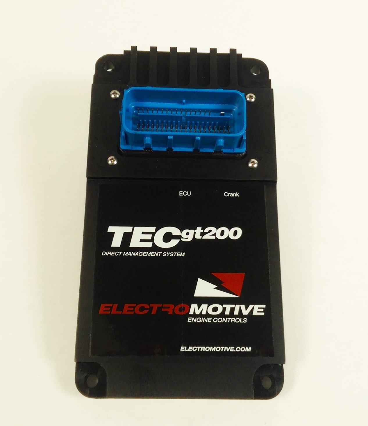
Electromotive TECs200 is a model in the Total Engine Control family. The manufacturer describes the TECs200 as a compact 200-series controller for supported one-, two- and four-cylinder applications. Manufacturer source.
Identification and software
Identify the exact model, serial, firmware and ignition-driver configuration before using a calibration or connecting a loom. WinTEC versions and hardware vary; the Electromotive manual archive separates the generations.
Wiring and pinout
Consult the model-specific manufacturer source and technical archive for the matching connector, firing order, ECU earths, injector drivers and ignition connections. Do not transfer TECgt200 or TECs200 positions to earlier TEC units. Where a complete exact-model pinout has not been verified, use the manufacturer documentation and verify the actual part number.
Availability
As of 17 November 2026, the manufacturer states it is not selling or repairing products. Electromotive notice. See the Electromotive family reference.
TECs200 connector pinout
All 73 positions from TECs200 manual v0.1, appendix IV pages 126–127. Blank source entries are marked ‘Not labelled in source’ and must not be assumed to be unused or spare. Position 37 is USB D− (white) in both the serial-communications table on page 67 and appendix IV on page 126. Verify the physical connector view and exact loom and hardware before connection; assignments are specific to TECs200.
| Pin | Manufacturer function | EMI harness colour | Wire gauge / type |
|---|---|---|---|
| 1 | Coil Shield | Bare (A) | 16 TST |
| 2 | Coil A1 | White(A) | 16 TST |
| 3 | Coil B1 | Red(A) | 16 TST |
| 4 | Coil C1 | Black(A) | 16 TST |
| 5 | DoC A1 | Blk/Gray | 20TXL |
| 6 | DoC B1 | Blk/Red | 20TXL |
| 7 | DoC C1 | Blk/Grn | 20TXL |
| 8 | Ground | Tan | 20TXL |
| 9 | Knock | Orange | 20TXL |
| 10 | Not labelled in source | — | — |
| 11 | Not labelled in source | — | — |
| 12 | Not labelled in source | — | — |
| 13 | Coil Shield | Bare (B) | 16 TST |
| 14 | Not labelled in source | — | — |
| 15 | Not labelled in source | — | — |
| 16 | Not labelled in source | — | — |
| 17 | Ground | Blk/Wht | 20TXL |
| 18 | Ground | Blk/Wht | 20TXL |
| 19 | 5V Ref | Gray/Red | 20TXL |
| 20 | 5V Ref | Gray/Red | 20TXL |
| 21 | 5V Ref | Gray/Red | 20TXL |
| 22 | GPI2 | Org/Red | 20TXL |
| 23 | GPI3 | Org/Grn | 20TXL |
| 24 | GPI4 | Org/Blue | 20TXL |
| 25 | GPI5 | Org/Ppl | 20TXL |
| 26 | GPI6 | Org/Pink | 20TXL |
| 27 | GPI7 | Org/Tan | 20TXL |
| 28 | GPI8 | Org/Yel | 20TXL |
| 29 | GPI9 | Org/Gray | 20TXL |
| 30 | Ground | Brown | 7cond |
| 31 | RXD | Orange | 7cond |
| 32 | TXD | Blue | 7cond |
| 33 | 12 volt in | Red/Wht | 18TXL |
| 34 | Speed In | Org/Blk | 20TXL |
| 35 | USB GND | Black/Shield | 7cond |
| 36 | USB PC5V | Red | 7cond |
| 37 | USB D- | White | 7cond |
| 38 | USB D+ | Green | 7cond |
| 39 | CAM in | Yel | 20TXL |
| 40 | CAM 2 | Yel/Ppl | — |
| 41 | Ground | Black/Wht | 20TXL |
| 42 | Crank Sensor in | Red | 24 TSP |
| 43 | Ground | Blk/Shld | 24 TSP |
| 44 | MAP | Green | 20TXL |
| 45 | TPS | Blue | 20TXL |
| 46 | CLT | Gray | 20TXL |
| 47 | MAT | White | 20TXL |
| 48 | EG RTD | Org/Wht | — |
| 49 | EGO Std | Purple | 20TXL |
| 50 | EGO W.B. | Ppl/Tan | — |
| 51 | CAN H | Yel/Pink | 20TXL |
| 52 | CAN L | Grn/Pink | 20TXL |
| 53 | 12 volt in | Red/Wht | 18TXL |
| 54 | Not labelled in source | — | — |
| 55 | Not labelled in source | — | — |
| 56 | Data log stat | Wht/Org | — |
| 57 | FPR | L.Grn | 20TXL |
| 58 | GPO1 | White/Blk | 20TXL |
| 59 | CE | Pink | 20TXL |
| 60 | IACB / GPO4 | D.Blu/Wht | 20TXL |
| 61 | IACA / GPO3 | D.Blu/Blk | 20TXL |
| 62 | Tach | Brown | 20TXL |
| 63 | GPO9 | Wht/Ppl | 20TXL |
| 64 | GPO8 | Wht/Blu | 20TXL |
| 65 | IACD / GPO6 | D.Grn/Wht | 20TXL |
| 66 | IACC / GPO5 | D.Grn/Blk | 20TXL |
| 67 | Inj1 | Yel/Blk | 20TXL |
| 68 | Inj2 | Yel/Red | 20TXL |
| 69 | Inj3 | Yel/Grn | 20TXL |
| 70 | Inj4 | Yel/Blue | 20TXL |
| 71 | Not labelled in source | — | — |
| 72 | Not labelled in source | — | — |
| 73 | Main Gnd | Black | 12TXL |
Supported configurations
The manufacturer manual lists four-stroke support for 1-, 2-, 3-, 4- and 6-cylinder even-fire engines (full sequential injection on four cylinders; phase-sequential and throttle-body injection on four or six cylinders; waste-spark ignition throughout) and two-stroke support for 1-, 2- and 3-cylinder engines with sequential or throttle-body injection and coil-per-plug ignition; staged injection is available on most setups. It describes a single sealed 73-pin Molex MX123 connector, RS-232 or USB tuning and CAN data output. The manual does not name the microcontroller. TECs200 manual v0.1, section 15.
Structured connector pinout
The 73 positions above are also given as a structured pin index with a redrawn wire-side connector face in Electromotive TECs200 connector pinout.