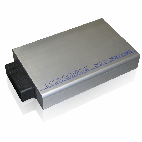
The 710 is Omex's programmable fuel-and-ignition ECU for a broad range of two- to twelve-cylinder configurations. The manufacturer lists distributor, wasted-spark and individual-coil ignition arrangements, two-stage and compatible continuous cam control, staged injectors, boost control, launch and flat shift. Features and outputs depend on firmware, hardware and engine configuration. Model-specific Omex manual · Omex engine-management range.
Connector and pinout
The Omex 710 hardware manual 2v11 gives connector pins at page 66 and wiring from page 68. FUEL outputs can be allocated as injection or PWM outputs, while some IGN outputs have configurable alternatives. Verify output allocation, driver capability and actual loom before wiring. Open the exact-model installation or hardware manual.
710 ECU loom-plug positions — manual 2v11
The table records the ECU plug on the end of the wiring harness, as described in OMEM710 hardware manual 2v11, section 29.2, page 66. Colour pairs are the manual's main colour and tracer for its described loom; confirm the actual cavity labels, loom and connector view. Functions may be configurable. A blank position in the source is not a spare assignment.
| Position | Manual loom colour | Function |
|---|---|---|
| 1A | Yellow/black | IGN1 |
| 2A | Yellow/violet | IGN6 |
| 3A | Brown/pink | FUEL8 |
| 4A | Red | Battery power |
| 5A | Black | Power ground 1 |
| 6A | Grey | Sensor ground |
| 7A | Black screened red | Crank sensor |
| 8A | Timing ground | |
| 9A | White/violet | Coolant temperature |
| 10A | White/yellow | MAP2 |
| 11A | Red screened red | Cam sensor |
| 12A | Yellow/grey | IGN2 |
| 1B | Yellow/orange | IGN4 |
| 2B | Yellow/green | IGN5 |
| 3B | Brown/violet | FUEL6 |
| 4B | Brown/black | FUEL1 |
| 5B | Brown/green | FUEL5 |
| 6B | Blue/white | MAP1 |
| 7B | Black | Power ground 2 |
| 8B | Brown/grey | FUEL7 |
| 9B | White/green | Air temperature |
| 10B | Blue | Knock sensor |
| 11B | White/orange | Oxygen sensor 2 |
| 12B | Yellow/red | IGN3 |
| 1C | Blue/grey | HIGHSIDE2 |
| 2C | Brown/orange | FUEL4 |
| 3C | Brown/yellow | FUEL2 |
| 4C | Not assigned in source | |
| 5C | Blue/black | HIGHSIDE1 |
| 6C | Brown/red | FUEL3 |
| 7C | White/red | Oxygen sensor 1 |
| 8C | Orange | Throttle position |
| 9C | Pink | 5 V output |
| 10C | Red/blue | Road speed sensor |
| 11C | White/pink | ALT POWER |
| 12C | Blue/yellow | Tacho |
The same 36 positions are drawn as a connector face, seen from the wiring-loom side, on Omex 710 connector pinout.
Software and setup
Omex lists MAP4000 for its current ECU range; check the exact unit, firmware and communications lead before attempting to connect. Record ECU serial and firmware, save the existing calibration, and confirm crank trigger, injector, coil, sensors and assigned outputs against the matching manual. Manufacturer startup calibrations require verification and adjustment for the actual engine.
Compare models and historical identities in the Omex family guide. Omex 710 product details.