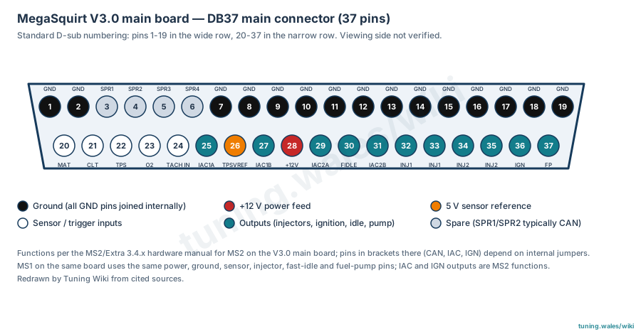
The MegaSquirt V3.0 main board connects to the vehicle through a single 37-pin DB37 (D-sub) connector. The pin assignment below is taken from the MS2/Extra 3.4.x hardware manual for MS2 on the V3.0 board (manufacturer documentation). The MegaManual wiring section gives the same power, ground, sensor, injector, fast-idle and fuel-pump pins for MegaSquirt-I on this board, and describes the stepper idle and ignition outputs as MS2 functions.
Connector summary
- Grounds: pins 1, 2 and 7 to 19. All ground pins are joined on the board; the manual recommends pin 1 for the crank sensor ground, pin 2 for the crank sensor shield, pin 7 for sensor ground and pins 15 to 19 as power grounds.
- Power: pin 28 is the main +12 V feed; pin 26 supplies 5 V to the throttle position sensor.
- Sensor inputs: 20 air temperature, 21 coolant temperature, 22 throttle position, 23 oxygen sensor, 24 crank (tach) input.
- Outputs: 32 and 33 injector bank 1, 34 and 35 injector bank 2 (7 A each), 30 fast idle (relay switching as standard), 37 fuel pump relay.
- Optional (internal jumpers): 3 and 4 (SPR1/SPR2) are typically CAN high and low; 5 and 6 (SPR3/SPR4) have no standard function; 25, 27, 29 and 31 are stepper idle outputs; 36 is a high-current ignition output, typically from a BIP373 driver. Which of these are connected depends on how the board was assembled.
The diagram uses standard D-sub numbering (pins 1 to 19 in the wide row, 20 to 37 in the narrow row); the viewing side is not verified. Check the assembly jumpers and builder's notes before wiring optional pins.
Sources
- MS2/V3.0 Hardware Manual, MS2/Extra 3.4.x, James Murray, dated 15 January 2016; main plug table and optional connections (section 3.3). Manufacturer documentation. Accessed 19 November 2026.
- MegaManual: Wiring and Sensors, Bruce Bowling and Al Grippo; DB37 pigtail wiring table for MegaSquirt-I and MS-II. Manufacturer documentation. Accessed 19 November 2026.
Diagram redrawn by Tuning Wiki from the MS2/V3.0 Hardware Manual.
Connector pinout
MegaSquirt V3.0 main board DB37 main connector. Functions are from the MS2/Extra 3.4.x hardware manual for MS2 on the V3.0 board (manufacturer documentation); functions shown there in brackets (CAN on SPR1/SPR2, stepper idle on 25/27/29/31, high-current ignition on 36) depend on internal jumpers and assembly. MegaSquirt-I on the same board uses the same power, ground, sensor, injector, fast-idle and fuel-pump pins per the MegaManual wiring section; the stepper idle and ignition outputs are MS2 functions there. All ground pins are joined internally. Face layout drawn with standard D-sub numbering; viewing side not verified.
View orientation is stated beside each photograph. Unknown functions remain in the pin index.
Main connector (DB37, 37 pins)
View: Standard D-sub numbering (pins 1-19 wide row, 20-37 narrow row); viewing side not verified
Select a pin in a photograph or the index to highlight it.
| Pin | Function / cavity | Confidence / source | Notes |
|---|---|---|---|
| Ground (crank sensor ground) Cavity: Populated |
Confirmed MS2/V3.0 Hardware Manual (MS2/Extra 3.4.x), main plug table |
Name GND; DIYAutoTune harness colour Black | |
| Ground (crank sensor shield) Cavity: Populated |
Confirmed MS2/V3.0 Hardware Manual (MS2/Extra 3.4.x), main plug table |
Name GND | |
| Spare 1, typically CAN high (jumper JS6) Cavity: Populated |
Confirmed MS2/V3.0 Hardware Manual (MS2/Extra 3.4.x), main plug table |
Name SPR1; DIYAutoTune harness colour Tan | |
| Spare 2, typically CAN low (jumper JS8) Cavity: Populated |
Confirmed MS2/V3.0 Hardware Manual (MS2/Extra 3.4.x), main plug table |
Name SPR2; DIYAutoTune harness colour Tan/Red | |
| Spare 3 (no standard function) Cavity: Populated |
Confirmed MS2/V3.0 Hardware Manual (MS2/Extra 3.4.x), main plug table |
Name SPR3; DIYAutoTune harness colour Tan/Green | |
| Spare 4 (no standard function) Cavity: Populated |
Confirmed MS2/V3.0 Hardware Manual (MS2/Extra 3.4.x), main plug table |
Name SPR4; DIYAutoTune harness colour Tan/Orange | |
| Ground (sensor ground) Cavity: Populated |
Confirmed MS2/V3.0 Hardware Manual (MS2/Extra 3.4.x), main plug table |
Name GND; DIYAutoTune harness colour Black/White | |
| Ground (spare) Cavity: Populated |
Confirmed MS2/V3.0 Hardware Manual (MS2/Extra 3.4.x), main plug table |
Name GND | |
| Ground (spare) Cavity: Populated |
Confirmed MS2/V3.0 Hardware Manual (MS2/Extra 3.4.x), main plug table |
Name GND | |
| Ground (spare) Cavity: Populated |
Confirmed MS2/V3.0 Hardware Manual (MS2/Extra 3.4.x), main plug table |
Name GND | |
| Ground (spare) Cavity: Populated |
Confirmed MS2/V3.0 Hardware Manual (MS2/Extra 3.4.x), main plug table |
Name GND | |
| Ground (spare) Cavity: Populated |
Confirmed MS2/V3.0 Hardware Manual (MS2/Extra 3.4.x), main plug table |
Name GND | |
| Ground (spare) Cavity: Populated |
Confirmed MS2/V3.0 Hardware Manual (MS2/Extra 3.4.x), main plug table |
Name GND | |
| Ground (spare) Cavity: Populated |
Confirmed MS2/V3.0 Hardware Manual (MS2/Extra 3.4.x), main plug table |
Name GND | |
| Ground (power ground) Cavity: Populated |
Confirmed MS2/V3.0 Hardware Manual (MS2/Extra 3.4.x), main plug table |
Name GND; DIYAutoTune harness colour Black | |
| Ground (power ground) Cavity: Populated |
Confirmed MS2/V3.0 Hardware Manual (MS2/Extra 3.4.x), main plug table |
Name GND; DIYAutoTune harness colour Black | |
| Ground (power ground) Cavity: Populated |
Confirmed MS2/V3.0 Hardware Manual (MS2/Extra 3.4.x), main plug table |
Name GND; DIYAutoTune harness colour Black | |
| Ground (power ground) Cavity: Populated |
Confirmed MS2/V3.0 Hardware Manual (MS2/Extra 3.4.x), main plug table |
Name GND; DIYAutoTune harness colour Black | |
| Ground (power ground) Cavity: Populated |
Confirmed MS2/V3.0 Hardware Manual (MS2/Extra 3.4.x), main plug table |
Name GND; DIYAutoTune harness colour Black | |
| Manifold air temperature sensor input Cavity: Populated |
Confirmed MS2/V3.0 Hardware Manual (MS2/Extra 3.4.x), main plug table |
Name MAT; DIYAutoTune harness colour Orange | |
| Coolant temperature sensor input Cavity: Populated |
Confirmed MS2/V3.0 Hardware Manual (MS2/Extra 3.4.x), main plug table |
Name CLT; DIYAutoTune harness colour Yellow | |
| Throttle position sensor input Cavity: Populated |
Confirmed MS2/V3.0 Hardware Manual (MS2/Extra 3.4.x), main plug table |
Name TPS; DIYAutoTune harness colour Light Blue | |
| Oxygen (lambda) sensor input Cavity: Populated |
Confirmed MS2/V3.0 Hardware Manual (MS2/Extra 3.4.x), main plug table |
Name O2; DIYAutoTune harness colour Pink | |
| Crank (tach) input Cavity: Populated |
Confirmed MS2/V3.0 Hardware Manual (MS2/Extra 3.4.x), main plug table |
Name TACH IN; DIYAutoTune harness colour White, shielded | |
| Stepper idle valve 1A (optional, internally connected) Cavity: Populated |
Confirmed MS2/V3.0 Hardware Manual (MS2/Extra 3.4.x), main plug table |
Name IAC1A; DIYAutoTune harness colour Blue/White; max 0.5 A | |
| 5 V supply for TPS Cavity: Populated |
Confirmed MS2/V3.0 Hardware Manual (MS2/Extra 3.4.x), main plug table |
Name TPSVREF; DIYAutoTune harness colour Gray; max 0.1 A | |
| Stepper idle valve 1B (optional) Cavity: Populated |
Confirmed MS2/V3.0 Hardware Manual (MS2/Extra 3.4.x), main plug table |
Name IAC1B; DIYAutoTune harness colour Blue/Red; max 0.5 A | |
| Main +12 V power feed Cavity: Populated |
Confirmed MS2/V3.0 Hardware Manual (MS2/Extra 3.4.x), main plug table |
Name +12V; DIYAutoTune harness colour Red; max < 1 A | |
| Stepper idle valve 2A (optional) Cavity: Populated |
Confirmed MS2/V3.0 Hardware Manual (MS2/Extra 3.4.x), main plug table |
Name IAC2A; DIYAutoTune harness colour Green/White; max 0.5 A | |
| Fast idle valve output (relay switching as standard) Cavity: Populated |
Confirmed MS2/V3.0 Hardware Manual (MS2/Extra 3.4.x), main plug table |
Name FIDLE; DIYAutoTune harness colour Light Green; max 0.1 A | |
| Stepper idle valve 2B (optional) Cavity: Populated |
Confirmed MS2/V3.0 Hardware Manual (MS2/Extra 3.4.x), main plug table |
Name IAC2B; DIYAutoTune harness colour Green/Red; max 0.5 A | |
| Injector bank 1 output Cavity: Populated |
Confirmed MS2/V3.0 Hardware Manual (MS2/Extra 3.4.x), main plug table |
Name INJ1; DIYAutoTune harness colour Blue; max 7 A | |
| Injector bank 1 output Cavity: Populated |
Confirmed MS2/V3.0 Hardware Manual (MS2/Extra 3.4.x), main plug table |
Name INJ1; DIYAutoTune harness colour Blue; max 7 A | |
| Injector bank 2 output Cavity: Populated |
Confirmed MS2/V3.0 Hardware Manual (MS2/Extra 3.4.x), main plug table |
Name INJ2; DIYAutoTune harness colour Green; max 7 A | |
| Injector bank 2 output Cavity: Populated |
Confirmed MS2/V3.0 Hardware Manual (MS2/Extra 3.4.x), main plug table |
Name INJ2; DIYAutoTune harness colour Green; max 7 A | |
| High-current ignition output (optional, typically BIP373 driver) Cavity: Populated |
Confirmed MS2/V3.0 Hardware Manual (MS2/Extra 3.4.x), main plug table |
Name IGN; DIYAutoTune harness colour Brown; max 7 A | |
| Fuel pump relay output Cavity: Populated |
Confirmed MS2/V3.0 Hardware Manual (MS2/Extra 3.4.x), main plug table |
Name FP; DIYAutoTune harness colour Violet; max 0.1 A |