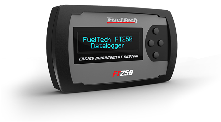
FuelTech FT250 is a Earlier FT generation engine-management unit. Earlier programmable fuel and ignition model covered with FT300 in FuelTech’s installation guide; the manual says trigger-wheel ignition requires a FirePRO or Fire4S in its documented setup. FuelTech model documentation · FuelTech range comparison.
Identification and software
Record the exact model, serial, harness, firmware and configured outputs; similarly named FT models may use different connectors and functions. Tuning software: ECU Manager / Datalogger (earlier generation). FuelTech software and compatibility.
Wiring and pinout
Use the model-specific manual and the current FuelTech manuals index for connector view, cavity numbering, fuse values, sensor grounds and injector-driver limits. The manufacturer wiring archive contains installation-specific examples; match the exact ECU and harness before wiring. Pin functions depend on the model, hardware and configured output.
See FuelTech engine-management family for other models and company background. FuelTech is based in Brazil and has a US operation in Georgia. Sources reviewed 17 November 2026.
24-way main connector
Pin numbers and wire functions below follow FuelTech's FT250 / FT300 manual, section 5.1; view the connector from the harness rear as shown in section 5.2. The FT250 uses only ignition output A; E, D, C and B are marked unavailable on FT250. The FT300 supports the additional ignition outputs. Check the actual configuration, sensor wiring, ignition driver and ground instructions.
| Pin | Function and harness wire |
|---|---|
| 1 | Tachometer output (green) |
| 2 | Auxiliary output 3 (yellow 3) |
| 3 | Intake air temperature input (white/blue) |
| 4 | Auxiliary output 2 (yellow 2) |
| 5 | Fuel/oil pressure or lambda input (white) |
| 6 | Auxiliary output 1 (yellow 1) |
| 7 | Coolant temperature input (pink) |
| 8 | Auxiliary output 4 (yellow 4) |
| 9 | Fuel/oil pressure or two-step input (blue) |
| 10 | Ignition output E (gray E) |
| 11 | Throttle position signal (orange) |
| 12 | Ignition output D (gray D) |
| 13 | MAP signal output (yellow/red) |
| 14 | Ignition output C (gray C) |
| 15 | Cam sync / FT250 MAP–MAF clamper, see note (green/yellow) |
| 16 | Ignition output B (gray B) |
| 17 | RPM signal input (shielded cable) |
| 18 | Ignition output A (gray A) |
| 19 | Battery negative / signal ground (black) |
| 20 | 5 V sensor supply (green/red) |
| 21 | Switched 12 V supply (red) |
| 22 | Power / chassis ground (black/white) |
| 23 | Fuel injector bank B negative (brown) |
| 24 | Fuel injector bank A negative (purple) |
FT250 source ambiguity: the wiring table identifies pin 15 as the MAP/MAF clamper connection for FT250, while the figure note appears to describe pin 13 as the clamper. Confirm the exact FT250 harness and corrected guidance with FuelTech before connecting this function.
A structured pin index and a redrawn connector diagram are in FuelTech FT250 and FT300 connector pinout.
Supported configurations
FuelTech's FT250 / FT300 manual (section 4, manufacturer specification) lists support for 1, 2, 3, 4, 5, 6, 8 and 10-cylinder engines up to 16,000 rpm, with an internal MAP sensor rated to 100 psi absolute (vacuum to 87 psi boost). Fuel is delivered through two independent injector banks driving up to twelve injectors in total, or more with an external peak-and-hold module; four auxiliary outputs are configurable. Ignition can be controlled from a distributor on both models, while crank-trigger-wheel ignition is listed for the FT300 only. Main fuel-map strategies are naturally aspirated by TPS, by TPS/MAP or by MAP, and turbocharged by MAP. FuelTech FT250 / FT300 manual, accessed 19 November 2026.
Not established
The microcontroller used in the FT250 and FT300 is not named in FuelTech's published documentation.