Bench connection pins
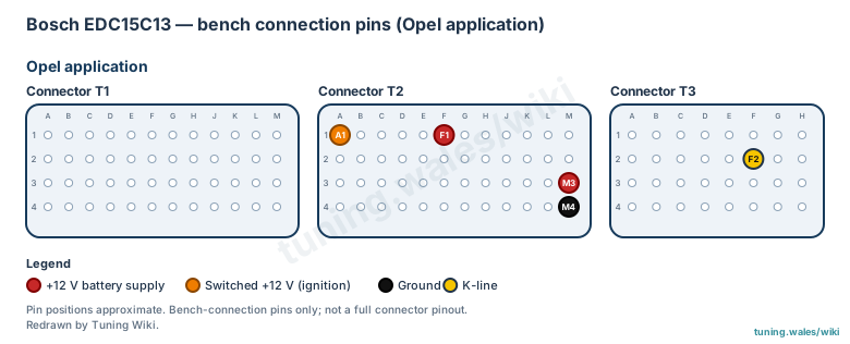
The Bosch EDC15C13 as fitted to Opel applications uses three connector blocks, labelled T1, T2 and T3. For off-car (bench) programming, five pins are used: T2 pins F1 and M3 carry the permanent battery +12 V supply, T2 pin A1 carries the switched (ignition) +12 V supply, T2 pin M4 is ground and T3 pin F2 is the K-line.
The diagram shows only these bench-connection pins and approximate positions within each connector block; it is not a full connector pinout. Pin assignments should be verified against the ECU label and hardware before the unit is powered.
Connector pinout
Bosch EDC15C13 as fitted to Opel applications. Bench-connection pins only; not a full connector pinout. Pin positions approximate.
View orientation is stated beside each photograph. Unknown functions remain in the pin index.
Bench connection
- Instructions
- Connect the listed pins to the flashing tool's bench cable as labelled; confirm against the ECU label and hardware before powering.
| Connector / pin | Connection role | Recorded function |
|---|---|---|
| Connector T2 / F1 | +12 V battery supply | +12 V battery supply (Suspected) |
| Connector T2 / M3 | +12 V battery supply | +12 V battery supply (Suspected) |
| Connector T2 / A1 | Switched +12 V (ignition) | Switched +12 V (ignition) (Suspected) |
| Connector T2 / M4 | Ground | Ground (Suspected) |
| Connector T3 / F2 | K-line | K-line (Suspected) |
Connector T2
View: As drawn; pin positions approximate
Select a pin in a photograph or the index to highlight it.
| Pin | Function / cavity | Confidence / source | Notes |
|---|---|---|---|
| +12 V battery supply Cavity: Populated |
Suspected | ||
| +12 V battery supply Cavity: Populated |
Suspected | ||
| Switched +12 V (ignition) Cavity: Populated |
Suspected | ||
| Ground Cavity: Populated |
Suspected |
Connector T3
View: As drawn; pin positions approximate
Select a pin in a photograph or the index to highlight it.
| Pin | Function / cavity | Confidence / source | Notes |
|---|---|---|---|
| K-line Cavity: Populated |
Suspected |