This page gives the 25-cavity ECU connector and the 7-cavity ignition control unit connector of the Volkswagen Digifant II system as published in a Cabriolet owner guide. The diagram applies to the 1990-1993 Cabriolet ECUs 037 906 022 CE, DE and EN (49-state and international) and to the 1990 California units CF, DD and EP, with a separate ignition control unit (191 905 351 B in the same guide). Other Digifant II installations were not covered by the source.
Connector pinout
The source draws the ECU connector as an upper row of cavities 1-13 and a lower row 14-25. Cavities 15, 20 and 24 carry no wire in the diagram and are shown with dashed outlines. Assigned functions are: start circuit (terminal 50) on pin 1; oxygen sensor on pin 2; fuel pump relay terminal 85 on pin 3; knock sensor pins 1 to 3 on pins 4, 5 and 7; the full-throttle and idle switches on pins 6 and 11; Hall sender pins 3 and 2 on pins 8 and 18; airflow temperature sensor pin 1 on pin 9; coolant temperature sensor on pin 10; injectors on pin 12; airflow sensor pins 3 and 2 on pins 17 and 21; idle stabiliser valve pins 2 and 3 on pins 22 and 23; ignition control unit pin 6 on pin 25; grounds on pins 13 (battery negative) and 19 (engine); Digifant relay terminal 87 on pin 14; and the air-conditioning compressor signal on pin 16. The oxygen-sensor wire is shown in two colours, for 1990 and for 1991 and later.
The ignition control unit connector is drawn with cavities 1 (coil), 2 (ground), 4 (positive input) and 6 (ECU); cavities 3, 5 and 7 carry no wire. The source does not state which side of either connector is viewed, so orientation is unverified.
The function labels use the guide's own wording and are graded as suspected: the guide is an owner-community document, not Volkswagen documentation. Diagram redrawn by Tuning Wiki from the Cabriolet DIY guide. See the Digifant II page for the system description and the Digifant I connector pinout for the 38-pin successor.
Sources
- Volkswagen Cabriolet DIY Guide: Digifant II vs. Digifant I, cabby-info.com, page 5 (Digifant II pinouts). Owner-community guide; undated. Accessed 19 November 2026.
Connector pinout
Volkswagen Digifant II 25-pin ECU and its separate ignition control unit as fitted to the 1990-1993 Cabriolet (037 906 022 CE / DE / EN, and the 1990 California CF / DD / EP), per the Cabriolet DIY guide's wiring diagram. Owner-community guide, not manufacturer documentation; pin functions are suspected. Terminal wording is the source's.
View orientation is stated beside each photograph. Unknown functions remain in the pin index.
25-pin ECU connector
View: As in source: 1-13 top, 14-25 bottom; view side not stated

Select a pin in a photograph or the index to highlight it.
| Pin | Function / cavity | Confidence / source | Notes |
|---|---|---|---|
| Start circuit (terminal 50) Cavity: Populated |
Suspected Cabby-info Digifant guide |
||
| Oxygen sensor Cavity: Populated |
Suspected Cabby-info Digifant guide |
||
| Fuel pump relay terminal 85 Cavity: Populated |
Suspected Cabby-info Digifant guide |
||
| Knock sensor pin 1 Cavity: Populated |
Suspected Cabby-info Digifant guide |
||
| Knock sensor pin 2 Cavity: Populated |
Suspected Cabby-info Digifant guide |
||
| Full-throttle / idle switches Cavity: Populated |
Suspected Cabby-info Digifant guide |
||
| Knock sensor pin 3 Cavity: Populated |
Suspected Cabby-info Digifant guide |
||
| Hall sender pin 3 Cavity: Populated |
Suspected Cabby-info Digifant guide |
||
| Airflow temperature sensor pin 1 Cavity: Populated |
Suspected Cabby-info Digifant guide |
||
| Coolant temperature sensor Cavity: Populated |
Suspected Cabby-info Digifant guide |
||
| Full-throttle / idle switches Cavity: Populated |
Suspected Cabby-info Digifant guide |
||
| Injectors Cavity: Populated |
Suspected Cabby-info Digifant guide |
||
| Ground at battery (-) Cavity: Populated |
Suspected Cabby-info Digifant guide |
||
| Digifant relay terminal 87 Cavity: Populated |
Suspected Cabby-info Digifant guide |
||
| Unknown function Cavity: Unknown |
Unknown | ||
| Air conditioning compressor Cavity: Populated |
Suspected Cabby-info Digifant guide |
||
| Airflow sensor pin 3 Cavity: Populated |
Suspected Cabby-info Digifant guide |
||
| Hall sender pin 2 Cavity: Populated |
Suspected Cabby-info Digifant guide |
||
| Ground on engine Cavity: Populated |
Suspected Cabby-info Digifant guide |
||
| Unknown function Cavity: Unknown |
Unknown | ||
| Airflow sensor pin 2 Cavity: Populated |
Suspected Cabby-info Digifant guide |
||
| Idle stabiliser valve pin 2 Cavity: Populated |
Suspected Cabby-info Digifant guide |
||
| Idle stabiliser valve pin 3 Cavity: Populated |
Suspected Cabby-info Digifant guide |
||
| Unknown function Cavity: Unknown |
Unknown | ||
| Ignition control unit pin 6 Cavity: Populated |
Suspected Cabby-info Digifant guide |
Ignition control unit connector (7-pin)
View: As in source; view side not stated
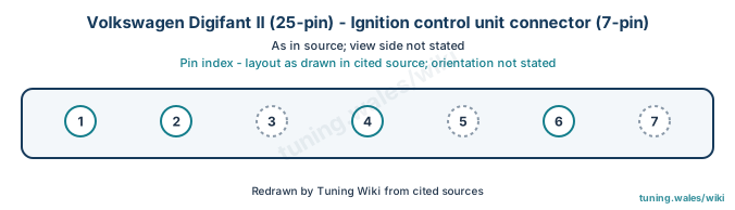
Select a pin in a photograph or the index to highlight it.
| Pin | Function / cavity | Confidence / source | Notes |
|---|---|---|---|
| Coil Cavity: Populated |
Suspected Cabby-info Digifant guide |
||
| Ground Cavity: Populated |
Suspected Cabby-info Digifant guide |
||
| Unknown function Cavity: Unknown |
Unknown | ||
| Positive input Cavity: Populated |
Suspected Cabby-info Digifant guide |
||
| Unknown function Cavity: Unknown |
Unknown | ||
| ECU Cavity: Populated |
Suspected Cabby-info Digifant guide |
||
| Unknown function Cavity: Unknown |
Unknown |