Scope
This page gives the terminal assignment of the Denso common-rail engine ECU fitted to the Mitsubishi Triton (Thailand) with the 4D56 and 4M41 diesel engines, as printed in Denso International Thailand's field-service document 00400554E of June 2005, section 15.2. The document states that the connector diagram and terminals are common to the 4D56 and 4M41. The Denso ECU numbers for these units (MA275800 series) are listed on Denso common-rail ECU. The assignment is manufacturer documentation for that vehicle; later or different Denso common-rail ECUs have different pinouts.
Connectors
- Connector A: terminals A01 to A81. The source table has no A56 row, so 80 terminals are listed. Unused positions are shown as no connection. It carries the injector drives, injector common supplies, suction control valve, sensor supplies and returns, crankshaft and cylinder sensors, glow-plug control, EGR motor, power grounds and several switch inputs.
- Connector B: terminals B01 to B40. It carries the accelerator position sensor, electronic throttle control, CAN, vehicle speed, starter and shift switches, tachometer output, ignition switch, signal ground and battery supplies.
The diagrams are numbered pin-index grids, not a physical face layout. Denso's figure draws the terminal layout in small print; that layout is not reproduced and its viewing direction is not stated in the text, so the orientation has not been verified. Signal symbols from the source are recorded in the notes of each pin. Diagram redrawn by Tuning Wiki from Denso document 00400554E.
Sources
- Denso International Thailand, Field Technical Service Department, Common Rail System for Mitsubishi Triton 4D56/4M41, document 00400554E, June 2005, section 15.2 Engine ECU Connector Diagram, terminal connections (1) to (3). Mirror: 00400554E. Accessed 19 November 2026.
Connector pinout
Denso common-rail engine ECU for the Mitsubishi Triton 4D56 and 4M41 (Thailand, 2005; Denso MA275800 numbers). Pin functions from the Denso International Thailand service document 00400554E, section 15.2 Engine ECU Connector Diagram, which states the connector terminals are common to the 4D56/4M41 model. Manufacturer documentation. A56 is not listed in the source.
View orientation is stated beside each photograph. Unknown functions remain in the pin index.
Connector A (A01-A81, 80 pins listed)
View: Pin index only. Terminal layout is drawn in the source figure but not reproduced; connector face orientation not stated in the text. Not verified.
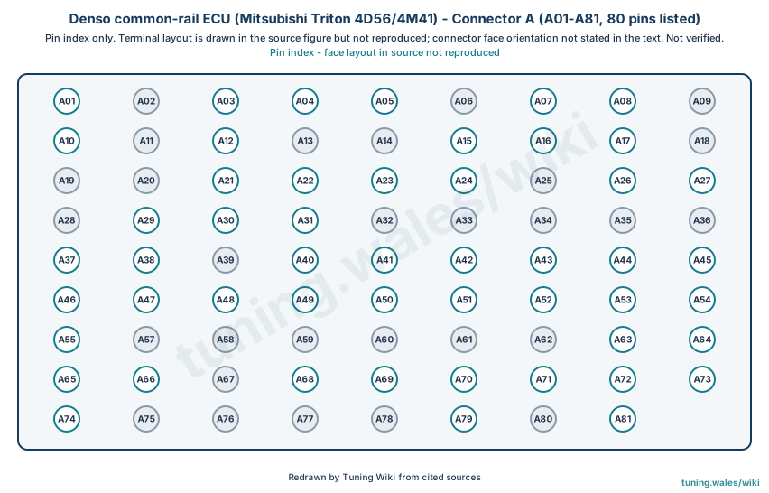
Select a pin in a photograph or the index to highlight it.
| Pin | Function / cavity | Confidence / source | Notes |
|---|---|---|---|
| Power Ground Cavity: Populated |
Confirmed | Symbol P-GND | |
| No connection Cavity: Unused |
Confirmed | ||
| Power Ground Cavity: Populated |
Confirmed | Symbol P-GND | |
| INJ#1/#4 BATT. Cavity: Populated |
Confirmed | Symbol COMMON 1 | |
| INJ#2/#3 BATT. Cavity: Populated |
Confirmed | Symbol COMMON 1 | |
| No connection Cavity: Unused |
Confirmed | ||
| EGR-DC Motor (-) Cavity: Populated |
Confirmed | Symbol EGR- | |
| EGR-DC Motor (+) Cavity: Populated |
Confirmed | Symbol EGR+ | |
| No connection Cavity: Unused |
Confirmed | ||
| SCV (Suction Control Valve) Cavity: Populated |
Confirmed | Symbol SCV+ | |
| No connection Cavity: Unused |
Confirmed | ||
| Air Conditioning 1 Switch Cavity: Populated |
Confirmed | Symbol A/C1 SW | |
| No connection Cavity: Unused |
Confirmed | ||
| No connection Cavity: Unused |
Confirmed | ||
| Throttle Solenoid Valve Cavity: Populated |
Confirmed | Symbol THR | |
| EngineWarning Light Cavity: Populated |
Confirmed | Symbol W | |
| SCV (Suction Control Valve) Cavity: Populated |
Confirmed | Symbol SCV | |
| No connection Cavity: Unused |
Confirmed | ||
| No connection Cavity: Unused |
Confirmed | ||
| No connection Cavity: Unused |
Confirmed | ||
| Injection 4 Drive (#2 Cylinder) Cavity: Populated |
Confirmed | Symbol TWV4 | |
| Injection 4 Drive (#2 Cylinder) Cavity: Populated |
Confirmed | Symbol TWV4 | |
| Injection 2 Drive (#3 Cylinder) Cavity: Populated |
Confirmed | Symbol TWV2 | |
| Injection 2 Drive (#3 Cylinder) Cavity: Populated |
Confirmed | Symbol TWV2 | |
| No connection Cavity: Unused |
Confirmed | ||
| Air Conditioning Relay Cavity: Populated |
Confirmed | Symbol A/C R | |
| FAN Relay Cavity: Populated |
Confirmed | Symbol C FAN R | |
| No connection Cavity: Unused |
Confirmed | ||
| SCV (Suction Control Valve) Cavity: Populated |
Confirmed | Symbol SCV- | |
| Test Switch Input Cavity: Populated |
Confirmed | Symbol TEST | |
| Air Conditioning 2 Switch Cavity: Populated |
Confirmed | Symbol A/C2 SW | |
| No connection Cavity: Unused |
Confirmed | ||
| No connection Cavity: Unused |
Confirmed | ||
| No connection Cavity: Unused |
Confirmed | ||
| No connection Cavity: Unused |
Confirmed | ||
| No connection Cavity: Unused |
Confirmed | ||
| Glow Plug Relay Cavity: Populated |
Confirmed | Symbol GLOW R | |
| Glow Light Cavity: Populated |
Confirmed | Symbol GLOW L | |
| No connection Cavity: Unused |
Confirmed | ||
| Injection 3 Drive (#4 Cylinder) Cavity: Populated |
Confirmed | Symbol TWV3 | |
| Injection 3 Drive (#4 Cylinder) Cavity: Populated |
Confirmed | Symbol TWV3 | |
| Injection 1 Drive (#1 Cylinder) Cavity: Populated |
Confirmed | Symbol TWV1 | |
| Injection 1 Drive (#1 Cylinder) Cavity: Populated |
Confirmed | Symbol TWV1 | |
| Crankshaft Position Sensor BATT Cavity: Populated |
Confirmed | Symbol A-VCC3 | |
| Cylinder Recognition Sensor BATT Cavity: Populated |
Confirmed | Symbol A-VCC4 | |
| Crankshaft Position Sensor Cavity: Populated |
Confirmed | Symbol NE+ | |
| Cylinder Recognition Sensor Cavity: Populated |
Confirmed | Symbol G+ | |
| Rail Pressure Sensor (PC Sensor) Cavity: Populated |
Confirmed | Symbol PFUEL | |
| Rail Pressure Sensor (B/UP) Cavity: Populated |
Confirmed | Symbol PFUEL | |
| Fuel Temperature Sensor Cavity: Populated |
Confirmed | Symbol THF | |
| Coolant Temperature Sensor Cavity: Populated |
Confirmed | Symbol THW | |
| Turbo Pressure Sensor Cavity: Populated |
Confirmed | Symbol BOOST | |
| EGR Position Sensor Cavity: Populated |
Confirmed | Symbol EGR LIFT | |
| Airflow Sensor Cavity: Populated |
Confirmed | Symbol AMF | |
| Air Temperature Sensor (W/AFS) Cavity: Populated |
Confirmed | Symbol EXT-A-TMP | |
| No connection Cavity: Unused |
Confirmed | ||
| No connection Cavity: Unused |
Confirmed | ||
| No connection Cavity: Unused |
Confirmed | ||
| No connection Cavity: Unused |
Confirmed | ||
| No connection Cavity: Unused |
Confirmed | ||
| No connection Cavity: Unused |
Confirmed | ||
| Rail Pressure Sensor (PC Sensor) Source Cavity: Populated |
Confirmed | Symbol A-VCC5 | |
| Turbo Pressure Sensor Source (5V) Cavity: Populated |
Confirmed | Symbol A-VCC6 | |
| Crankshaft Position Sensor Ground Cavity: Populated |
Confirmed | Symbol NE- | |
| Cylinder Recognition Sensor Ground Cavity: Populated |
Confirmed | Symbol G- | |
| No connection Cavity: Unused |
Confirmed | ||
| Rail Pressure Sensor Earth Cavity: Populated |
Confirmed | Symbol PFUEL RTN | |
| Air Temperature Sensor, Fuel Temperature Sensor Earth Cavity: Populated |
Confirmed | Symbol THF RTN | |
| Coolant Temperature Sensor Earth Cavity: Populated |
Confirmed | Symbol THW RTN | |
| Turbo Pressure Sensor Earth Cavity: Populated |
Confirmed | Symbol BOOST RTN | |
| EGR Position Sensor Earth Cavity: Populated |
Confirmed | Symbol EGR LIFT RTS | |
| Airflow Sensor Earth Cavity: Populated |
Confirmed | Symbol AMF-RTN | |
| Air Temperature Sensor Earth (W/FAS) Cavity: Populated |
Confirmed | Symbol EXT-A-RTN | |
| No connection Cavity: Unused |
Confirmed | ||
| No connection Cavity: Unused |
Confirmed | ||
| No connection Cavity: Unused |
Confirmed | ||
| No connection Cavity: Unused |
Confirmed | ||
| Air Temperature Sensor Cavity: Populated |
Confirmed | Symbol THA | |
| No connection Cavity: Unused |
Confirmed | ||
| Electoronic Throttle Control (Sub) Cavity: Populated |
Confirmed | Symbol ETCP-S |
Connector B (B01-B40)
View: Pin index only. Terminal layout is drawn in the source figure but not reproduced; connector face orientation not stated in the text. Not verified.
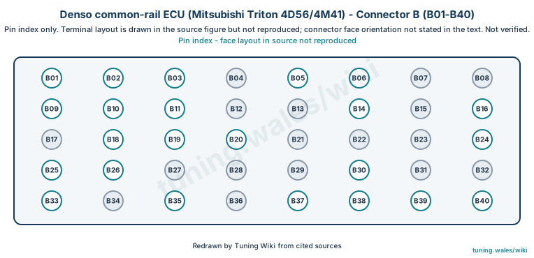
Select a pin in a photograph or the index to highlight it.
| Pin | Function / cavity | Confidence / source | Notes |
|---|---|---|---|
| Accelerator Position Sensor (Main) Source Cavity: Populated |
Confirmed | Symbol A-VCC 1 | |
| Accelerator Position Sensor (Main) Cavity: Populated |
Confirmed | Symbol APS 1 | |
| Accelerator Position Sensor (Main) Earth Cavity: Populated |
Confirmed | Symbol APS 1 GND | |
| No connection Cavity: Unused |
Confirmed | ||
| Electoronic Throttle Control (Main) Cavity: Populated |
Confirmed | Symbol ETCP-M | |
| CAN L (W/Resister) Cavity: Populated |
Confirmed | Symbol CAN1-L | |
| No connection Cavity: Unused |
Confirmed | ||
| No connection Cavity: Unused |
Confirmed | ||
| Accelerator Position Sensor (Sub) Source Cavity: Populated |
Confirmed | Symbol A-VCC 2 | |
| Accelerator Position Sensor (Sub) Cavity: Populated |
Confirmed | Symbol APS 2 | |
| Accelerator Position Sensor (Sub) Earth Cavity: Populated |
Confirmed | Symbol APS 2 GND | |
| No connection Cavity: Unused |
Confirmed | ||
| No connection Cavity: Unused |
Confirmed | ||
| CAN H (W/Resister) Cavity: Populated |
Confirmed | Symbol CAN1-H | |
| No connection Cavity: Unused |
Confirmed | ||
| Vehicle Speed Sensor Cavity: Populated |
Confirmed | Symbol SPD | |
| No connection Cavity: Unused |
Confirmed | ||
| Starter Switch Cavity: Populated |
Confirmed | Symbol STA-SW | |
| 1st Shift Switch Cavity: Populated |
Confirmed | Symbol MT 1ST SW | |
| Reverse Shift Switch Cavity: Populated |
Confirmed | Symbol MT REV SW | |
| No connection Cavity: Unused |
Confirmed | ||
| No connection Cavity: Unused |
Confirmed | ||
| No connection Cavity: Unused |
Confirmed | ||
| Control (ECCS) Relay (W/ DIODE) Cavity: Populated |
Confirmed | Symbol M-REL | |
| Tacho Meter Cavity: Populated |
Confirmed | Symbol TACHO | |
| Ignition Switch Cavity: Populated |
Confirmed | Symbol IG-SW | |
| No connection Cavity: Unused |
Confirmed | ||
| No connection Cavity: Unused |
Confirmed | ||
| No connection Cavity: Unused |
Confirmed | ||
| Power Steering Switch Cavity: Populated |
Confirmed | Symbol PS-SW | |
| No connection Cavity: Unused |
Confirmed | ||
| No connection Cavity: Unused |
Confirmed | ||
| Signal Ground Cavity: Populated |
Confirmed | Symbol C-GND | |
| No connection Cavity: Unused |
Confirmed | ||
| Electronic Throttle Control Motor (+) Cavity: Populated |
Confirmed | Symbol ETC+ | |
| No connection Cavity: Unused |
Confirmed | ||
| Electronic Throttle Control Motor (-) Cavity: Populated |
Confirmed | Symbol ETC- | |
| Battery Cavity: Populated |
Confirmed | Symbol +BP | |
| Battery Cavity: Populated |
Confirmed | Symbol +BP | |
| Battery (Back-up, W/Monitor) Cavity: Populated |
Confirmed | Symbol BATT |