Removed text is struck through; added text is highlighted.
Ford EEC-IV is the engine-control module these notes test through its own self-test, using a STAR fast/slow code reader on EEC-IV/EFI systems. The module checks sensors, switches and actuators, stores the result as two-digit codes, and pulses those codes out of a three-pin self-test socket in the loom beside the ECU. A displayed 11 means the check that has just run found no fault. Code 50, seen during the engine-running test, confirms that the module is a European-specification unit and needs no action.
The notes describe this self-test as more detailed than earlier EEC-IV self-tests, because this module’s self-test is more capable. Workshop manuals for individual vehicles are written in slow codes. Fast codes are one hundred times faster, so the STAR tester’s fast/slow switch must be in the slow position for every procedure below. The notes do not list model years. Treat the steps as the procedure for the EEC-IV/EFI module that uses this self-test, and follow the workshop manual for the vehicle when a pinpoint test is required.
The three sequences have to be completed in order. Finish the engine-off test, then the continuous-code test, then the engine-running test. Each one must be finished, and any code it raises must be corrected, before the next sequence is started. Running them in that order is how the notes say a system fault is actually found. How to operate the reader itself is on the EEC-IV STAR code reader page; the sequences below include every tester step the notes give, so the module procedure can be followed from this page.
Processor and applications
EEC-IV is built around the Intel-designed 8/16-bit 8061 microprocessor, a close relative of the 8096 that was made for Ford and not sold commercially (secondary sources: Wikipedia articles on Ford EEC and the Intel 8061). The first module held 8 KB of mask ROM and 128 bytes of RAM; later modules used larger or separate memory devices. EEC-IV first appeared on the 1983½ Escort EFI with the 1.6 litre engine, and the 1984 applications included the 2.3 litre HSC, the 2.3 litre turbocharged EFI engine and 2.8 litre truck engines. Its successor, EEC-V, uses an enhanced 8065 processor. These are secondary-source statements; no engine-by-engine list for the European EFI module covered by the self-test below has been established, and connector pin assignments vary by vehicle and year, so a single EEC-IV pinout is not given here.
Self-test socket
The diagnostics connector is normally in the wiring under the glovebox, close to the ECU. The self-test output is a three-pin plug in that loom. The STAR reader is built with two connectors because cars of this period use at least two different plugs.
Identify the diagnostics plug by wire colour before connecting anything. The diagnostics wires are brown, brown/green and blue/green. The octane-adjust plug is a separate connector in the same area, and an idle-adjust wire may also be present. Both of those adjustment wires are disconnected for the test if they are grounded, and both are reconnected when the tester comes off.
Later cars, type 1
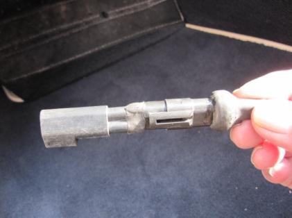
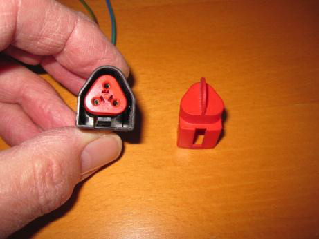
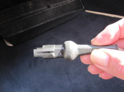
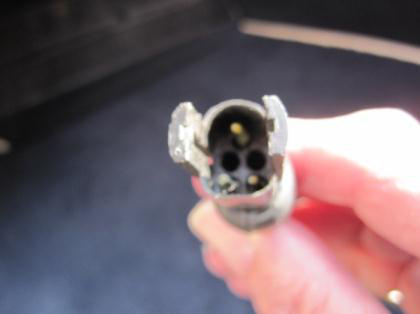
On the later arrangement the extra connector is left fitted to the STAR tester. The black connector is the diagnostics plug. Its red cap comes off by pressing the clip on the bottom of the connector, at the back. The white connector is the octane adjust.
Later-car connector, side view. The black diagnostics plug is the one that stays mated to the tester’s additional connector.
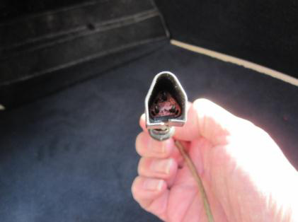
End view of the same later-car plug, looking into the housing.
Red cap removed. The cap unclips from the bottom of the connector at the back and leaves the three terminals exposed.
Earlier cars, type 2
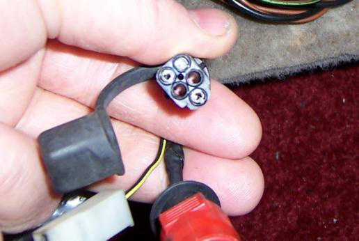
On the earlier arrangement the additional connector has to come off the STAR tester before the car’s plug will mate. The diagnostics connector sits under the black cover. The red cover is the octane adjust.
Earlier-car plug with the black cover pulled back. The notes identify diagnostics by that black cover and octane adjust by the red cover. A white plug is in the same loom in this photograph; the notes do not name it. Confirm diagnostics by the brown, brown/green and blue/green wires before connecting.
Earlier-car connector, side view, after the additional tester connector has been removed.
End view of the earlier-car diagnostics plug.
How the module reports a code
If the low-battery warning is on the reader, stop. Switch the ignition off and switch the tester off, fit a new internal 9 V battery, and run the whole self-test again. A low battery invalidates the test in progress.
Once the reader is in test and shows its TEST symbol, it is ready to take codes from the module. The module then emits a series. Any codes it gives are repeated once. A single fault, or no fault, stays on the display, and the LED flashes to show that the code is being repeated. The codes are the faults present at the time of that test. Code 11 is a pass for the test that has just run. If a fault is still present after an 11, the notes say to carry out the fuel checks.
The reader keeps every code it receives. After the self-test, leave the tester switched on: memory is cleared by switching the tester off, and it is also cleared by releasing the square red switch and putting it back to TEST. Memory recall is on the STAR page.
Engine-off self-test
This pass checks sensors and actuators in the rest position. It then opens a wiggle test so a wiring or connector fault can be made to show itself. Do not crank the engine.
Disconnect the octane-adjust wire and the idle-adjust wire if either is grounded. Switch the air conditioning off. Select neutral and make sure the handbrake is fully applied.
Connect the STAR tester to the three-pin self-test socket. Switch the tester on with the ON/OFF button. Confirm that the low-battery warning is not displayed. Press the 2-digit button, press Slow, then press MEM/TEST. The TEST symbol means the reader will accept codes from the module.
Switch the ignition on and do not crank. After a short pause, while the module is powering up, it enters the self-test.
Watch the display and write down every code. The module looks for normal engine-off sensor readings and for the state of the input switches. Any value outside limits is logged, and the module then emits the series. Code 11 here means no fault was found in this pass. Any other code is a fault present now.
Code 10 comes up next. That is the command to start the wiggle test: the module is in wiggle mode. Move the wiring and the connectors while watching the LED. A flash is a fault. Note where the harness was when the LED flashed.
Switch the ignition off. Press MEM/TEST. Switch the tester off, but leave it connected.
Correct every code from the code list and every wiring fault found while wiggling. When the repair is done, run the whole self-test again from the engine-off pass. Only move on to the continuous-code test once this pass is clean.
Continuous-code self-test
This pass checks for normal running values. The engine is started before the reader is put into test.
Start the engine. Switch the tester on and confirm there is no low-battery warning. Press the 2-digit button, press Slow, wait about four seconds, then press MEM/TEST. The TEST symbol means the reader is ready.
Write down every code. The module looks at the sensor readings and at the state of the input switches. A value outside limits is logged and then emitted. The same display rule applies: a series is repeated once; a single code stays up and the LED flashes while it is repeated. Code 11 means this pass found no fault. Any other code is a fault present during this running check.
Press MEM/TEST. Switch the tester off. Switch the ignition off. Leave the tester connected.
Correct the codes from the code list, then repeat the whole self-test. The notes’ closing line for this section still says “proceed to the continuous self-test” and refers to codes recorded in steps 4 or 5. That wording is the engine-off close, and this section does not have those steps. The order given at the start is engine-off, then continuous codes, then the engine-running test, so the running test is next once the continuous pass is clean.
Engine-running self-test
The module uses this pass for dynamic checks. It will refuse those checks if the coolant is cold, the transmission is not in neutral, or the air conditioning is on. Those conditions are reported as codes before the engine speed is raised, and the dynamic sequence does not start.
Switch the tester on. Confirm there is no low-battery warning. Press the 2-digit button, press Slow, wait about four seconds, then press MEM/TEST. Wait for the TEST symbol.
Switch the ignition on, wait three seconds, and then start the engine. The pause is there so the module has initialised before the engine is cranked.
Code 50 should be displayed. Code 50 confirms a European-specification module. No action is required for 50 itself.
A series of codes may appear at this point. They mean the module has seen coolant that is not hot enough, a transmission that is not in neutral, or air conditioning that is still on. If any code appears here, the module will not go on to the dynamic checks. Switch the tester off, press MEM/TEST, switch the engine off, correct the cause, and repeat the whole engine-running test.
Engine speed then rises on its own. The module has entered the dynamic sequence. It checks switches and inputs against the engine-running limits, and it checks the actuators it controls by simulating conditions and comparing each actuator’s response with the programmed parameters. Faults are logged in the module and are displayed later; they are not shown during the speed increase.
Code 10 is the command to blip the throttle. Do it as soon as 10 appears. The module has to see engine speed go above 3,000 rpm.
Code 44 may appear. It means the module did not see a large enough change in engine speed, so the blip was missed or was not hard enough. Press MEM/TEST, switch off the tester and the engine, go back to step 1, and repeat the whole engine-running test. If 44 does not appear, continue.
Code 11 or the fault codes then appear. These are faults that occurred at any time during this procedure, including the dynamic checks.
If there are fault codes, press MEM/TEST, switch the tester off, correct them from the code list, and repeat the whole engine-running test. If there is no fault, 11 stays displayed and the test continues.
Code 60 should then be displayed. The module has locked ignition timing and locked the idle-speed control valve at preset values. It will not compensate timing or idle. Basic ignition timing has to be set in this mode. If the throttle has to be held slightly open to check or adjust the timing, the notes say to use a feeler gauge. Code 60 is only held for about ten minutes, so that the locked setting cannot be left on long enough to damage the engine. If code 70 appears before the timing has been set, 70 means the module has unlocked the code-60 state. Continue to the shutdown step, then repeat the whole engine-running test to obtain 60 again and set the timing inside that window.
Switch the engine off. Press MEM/TEST. Switch the tester off and disconnect it. Reconnect the octane-adjust wire, the idle-adjust wire, or both, if they were disconnected at the start.
Service codes
The same component can raise as many as three different codes. Those codes carry a more specific failure mode, and the notes say that detail exists to validate the system during manufacture. In service, the repair for two different codes on the same component can be the same job. Coolant-temperature codes 23 and 33 are the example given: both point at the coolant-temperature sensor, and both are sent to the same pinpoint. Vane-air-meter No. 1 codes are 12, 22, 32 and 41. Vane-air-meter No. 2 codes are 16, 26, 36 and 42. The notes do not define what separates No. 1 from No. 2, apart from the special case for code 16 below, so the two groups stay separate here.
Where the action is a workshop page number, that pinpoint is not in these notes. The page number is the cross-reference the notes recorded. Several entries were left as a blank page number; those are marked as not recorded. Codes that do not appear in the list were not given.
CodeWhat it indicatesAction
10Command codeWiggle test during the engine-off pass, or blip the throttle during the engine-running pass. It is an instruction, not a failed part.
11System passNo fault in the pass that has just run. If a fault is still present on the vehicle, carry out the fuel checks.
12Vane air meter No. 1Workshop pinpoint, page 14.
13Engine coolant temperature sensorWorkshop pinpoint, page 15.
14Vane air temperature sensorWorkshop pinpoint, page 19.
15Throttle position sensorWorkshop pinpoint, page 16.
16Vane air meter No. 2If 16 is the only code in the engine-running self-test, check base idle speed using the procedure on workshop page 28. If any other code is present as well, use workshop page 17.
18Battery voltage lowCheck the charging system and the battery. If both are sound, fit a new EEC-IV module.
21Ignition signal erraticWorkshop pinpoint, page 18.
22Vane air meter No. 1Workshop pinpoint, page 19.
23Engine coolant temperature sensorWorkshop pinpoint, page 21. In service this can be the same repair as code 33.
24Vane air temperature sensorWorkshop pinpoint, page 19.
25Throttle position sensorWorkshop pinpoint, page 22.
26Vane air meter No. 2Workshop pinpoint, page 17.
31ROM/RAM failureBreakout-box checks. The notes leave the workshop page number blank.
32Vane air meter No. 1Workshop pinpoint, page 19.
33Engine coolant temperature sensorWorkshop pinpoint, page 21. In service this can be the same repair as code 23.
34Vane air temperature sensorWorkshop pinpoint, page 19.
35Throttle position sensorWorkshop pinpoint, page 22.
36Vane air meter No. 2Workshop pinpoint, page 17.
41Vane air meter No. 1Workshop pinpoint, page 14.
42Vane air meter No. 2Workshop pinpoint, page 17.
43Throttle position sensorWorkshop pinpoint, page 22.
44Blip test not performedThe throttle blip did not raise engine speed enough. Repeat the self-test.
45Vehicle speed sensorBreakout-box test 35.
46Idle speed control valve failureWorkshop pinpoint, page 33.
47Low idle speed during the testWorkshop pinpoint, page 33, and the fuel checks. The notes leave the fuel-check page number blank.
50European module fittedNo action. This is the confirmation, during the engine-running test, that the module is the European specification.
51Air conditioning onSwitch the air conditioning off and repeat the self-test. The dynamic checks will not start while it is on.
52Vehicle in drive during the testSelect neutral or park and repeat the self-test.
53Octane adjust groundedDisconnect the adjustment wire and repeat the self-test. Check the wiring. The notes leave the wiring page number blank.
54Octane adjust groundedDisconnect the adjustment wire and repeat the self-test. Check the wiring. The notes leave the wiring page number blank. Recorded separately from 53, with the same action.
55Idle speed adjust groundedDisconnect the adjustment wire and repeat the self-test. Check the wiring. The notes leave the wiring page number blank.
57Throttle moved during the testRepeat the self-test. The throttle has to stay still except for the deliberate blip when code 10 is displayed.
60Service set modeCheck and adjust ignition timing. Timing and the idle-speed control valve are locked to preset values, with no compensation, for about ten minutes.
67Fuel-rail temperature switchWorkshop pinpoint, page 24.
70Out of service setThe module has left code 60 and unlocked timing and idle control. The notes give no separate repair for 70. If it appears before timing has been set, shut down and repeat the engine-running test to obtain 60 again.
Code 10, code 11, code 44, code 50, code 51, code 52, code 57, code 60 and code 70 are read in the sequence above. They are part of running the test, not a reason to replace a sensor on their own. A component code still needs the pinpoint the table names; these notes stop at the code and the cross-reference.
Sources
Ford EEC, Wikipedia (secondary). EEC-IV introduction on the 1983½ Escort EFI, 1984 engines, Intel 8061 processor, memory sizes. Accessed 19 November 2026.
Intel 8061, Wikipedia (secondary). Relationship to the 8096 and second sourcing. Seen in search summary, 19 November 2026.
Rendered revisions
Open each version to inspect formatting, tables and photographs.
Revision 2: Ford EEC-IV
Ford EEC-IV is the engine-control module these notes test through its own self-test, using a STAR fast/slow code reader on EEC-IV/EFI systems. The module checks sensors, switches and actuators, stores the result as two-digit codes, and pulses those codes out of a three-pin self-test socket in the loom beside the ECU. A displayed 11 means the check that has just run found no fault. Code 50, seen during the engine-running test, confirms that the module is a European-specification unit and needs no action.
The notes describe this self-test as more detailed than earlier EEC-IV self-tests, because this module’s self-test is more capable. Workshop manuals for individual vehicles are written in slow codes. Fast codes are one hundred times faster, so the STAR tester’s fast/slow switch must be in the slow position for every procedure below. The notes do not list model years. Treat the steps as the procedure for the EEC-IV/EFI module that uses this self-test, and follow the workshop manual for the vehicle when a pinpoint test is required.
The three sequences have to be completed in order. Finish the engine-off test, then the continuous-code test, then the engine-running test. Each one must be finished, and any code it raises must be corrected, before the next sequence is started. Running them in that order is how the notes say a system fault is actually found. How to operate the reader itself is on the EEC-IV STAR code reader page; the sequences below include every tester step the notes give, so the module procedure can be followed from this page.
Processor and applications
EEC-IV is built around the Intel-designed 8/16-bit 8061 microprocessor, a close relative of the 8096 that was made for Ford and not sold commercially (secondary sources: Wikipedia articles on Ford EEC and the Intel 8061). The first module held 8 KB of mask ROM and 128 bytes of RAM; later modules used larger or separate memory devices. EEC-IV first appeared on the 1983½ Escort EFI with the 1.6 litre engine, and the 1984 applications included the 2.3 litre HSC, the 2.3 litre turbocharged EFI engine and 2.8 litre truck engines. Its successor, EEC-V, uses an enhanced 8065 processor. These are secondary-source statements; no engine-by-engine list for the European EFI module covered by the self-test below has been established, and connector pin assignments vary by vehicle and year, so a single EEC-IV pinout is not given here.
Self-test socket
The diagnostics connector is normally in the wiring under the glovebox, close to the ECU. The self-test output is a three-pin plug in that loom. The STAR reader is built with two connectors because cars of this period use at least two different plugs.
Identify the diagnostics plug by wire colour before connecting anything. The diagnostics wires are brown, brown/green and blue/green. The octane-adjust plug is a separate connector in the same area, and an idle-adjust wire may also be present. Both of those adjustment wires are disconnected for the test if they are grounded, and both are reconnected when the tester comes off.
Later cars, type 1
On the later arrangement the extra connector is left fitted to the STAR tester. The black connector is the diagnostics plug. Its red cap comes off by pressing the clip on the bottom of the connector, at the back. The white connector is the octane adjust.
Later-car connector, side view. The black diagnostics plug is the one that stays mated to the tester’s additional connector.End view of the same later-car plug, looking into the housing.Red cap removed. The cap unclips from the bottom of the connector at the back and leaves the three terminals exposed.
Earlier cars, type 2
On the earlier arrangement the additional connector has to come off the STAR tester before the car’s plug will mate. The diagnostics connector sits under the black cover. The red cover is the octane adjust.
Earlier-car plug with the black cover pulled back. The notes identify diagnostics by that black cover and octane adjust by the red cover. A white plug is in the same loom in this photograph; the notes do not name it. Confirm diagnostics by the brown, brown/green and blue/green wires before connecting.Earlier-car connector, side view, after the additional tester connector has been removed.End view of the earlier-car diagnostics plug.
How the module reports a code
If the low-battery warning is on the reader, stop. Switch the ignition off and switch the tester off, fit a new internal 9 V battery, and run the whole self-test again. A low battery invalidates the test in progress.
Once the reader is in test and shows its TEST symbol, it is ready to take codes from the module. The module then emits a series. Any codes it gives are repeated once. A single fault, or no fault, stays on the display, and the LED flashes to show that the code is being repeated. The codes are the faults present at the time of that test. Code 11 is a pass for the test that has just run. If a fault is still present after an 11, the notes say to carry out the fuel checks.
The reader keeps every code it receives. After the self-test, leave the tester switched on: memory is cleared by switching the tester off, and it is also cleared by releasing the square red switch and putting it back to TEST. Memory recall is on the STAR page.
Engine-off self-test
This pass checks sensors and actuators in the rest position. It then opens a wiggle test so a wiring or connector fault can be made to show itself. Do not crank the engine.
Disconnect the octane-adjust wire and the idle-adjust wire if either is grounded. Switch the air conditioning off. Select neutral and make sure the handbrake is fully applied.
Connect the STAR tester to the three-pin self-test socket. Switch the tester on with the ON/OFF button. Confirm that the low-battery warning is not displayed. Press the 2-digit button, press Slow, then press MEM/TEST. The TEST symbol means the reader will accept codes from the module.
Switch the ignition on and do not crank. After a short pause, while the module is powering up, it enters the self-test.
Watch the display and write down every code. The module looks for normal engine-off sensor readings and for the state of the input switches. Any value outside limits is logged, and the module then emits the series. Code 11 here means no fault was found in this pass. Any other code is a fault present now.
Code 10 comes up next. That is the command to start the wiggle test: the module is in wiggle mode. Move the wiring and the connectors while watching the LED. A flash is a fault. Note where the harness was when the LED flashed.
Switch the ignition off. Press MEM/TEST. Switch the tester off, but leave it connected.
Correct every code from the code list and every wiring fault found while wiggling. When the repair is done, run the whole self-test again from the engine-off pass. Only move on to the continuous-code test once this pass is clean.
Continuous-code self-test
This pass checks for normal running values. The engine is started before the reader is put into test.
Start the engine. Switch the tester on and confirm there is no low-battery warning. Press the 2-digit button, press Slow, wait about four seconds, then press MEM/TEST. The TEST symbol means the reader is ready.
Write down every code. The module looks at the sensor readings and at the state of the input switches. A value outside limits is logged and then emitted. The same display rule applies: a series is repeated once; a single code stays up and the LED flashes while it is repeated. Code 11 means this pass found no fault. Any other code is a fault present during this running check.
Press MEM/TEST. Switch the tester off. Switch the ignition off. Leave the tester connected.
Correct the codes from the code list, then repeat the whole self-test. The notes’ closing line for this section still says “proceed to the continuous self-test” and refers to codes recorded in steps 4 or 5. That wording is the engine-off close, and this section does not have those steps. The order given at the start is engine-off, then continuous codes, then the engine-running test, so the running test is next once the continuous pass is clean.
Engine-running self-test
The module uses this pass for dynamic checks. It will refuse those checks if the coolant is cold, the transmission is not in neutral, or the air conditioning is on. Those conditions are reported as codes before the engine speed is raised, and the dynamic sequence does not start.
Switch the tester on. Confirm there is no low-battery warning. Press the 2-digit button, press Slow, wait about four seconds, then press MEM/TEST. Wait for the TEST symbol.
Switch the ignition on, wait three seconds, and then start the engine. The pause is there so the module has initialised before the engine is cranked.
Code 50 should be displayed. Code 50 confirms a European-specification module. No action is required for 50 itself.
A series of codes may appear at this point. They mean the module has seen coolant that is not hot enough, a transmission that is not in neutral, or air conditioning that is still on. If any code appears here, the module will not go on to the dynamic checks. Switch the tester off, press MEM/TEST, switch the engine off, correct the cause, and repeat the whole engine-running test.
Engine speed then rises on its own. The module has entered the dynamic sequence. It checks switches and inputs against the engine-running limits, and it checks the actuators it controls by simulating conditions and comparing each actuator’s response with the programmed parameters. Faults are logged in the module and are displayed later; they are not shown during the speed increase.
Code 10 is the command to blip the throttle. Do it as soon as 10 appears. The module has to see engine speed go above 3,000 rpm.
Code 44 may appear. It means the module did not see a large enough change in engine speed, so the blip was missed or was not hard enough. Press MEM/TEST, switch off the tester and the engine, go back to step 1, and repeat the whole engine-running test. If 44 does not appear, continue.
Code 11 or the fault codes then appear. These are faults that occurred at any time during this procedure, including the dynamic checks.
If there are fault codes, press MEM/TEST, switch the tester off, correct them from the code list, and repeat the whole engine-running test. If there is no fault, 11 stays displayed and the test continues.
Code 60 should then be displayed. The module has locked ignition timing and locked the idle-speed control valve at preset values. It will not compensate timing or idle. Basic ignition timing has to be set in this mode. If the throttle has to be held slightly open to check or adjust the timing, the notes say to use a feeler gauge. Code 60 is only held for about ten minutes, so that the locked setting cannot be left on long enough to damage the engine. If code 70 appears before the timing has been set, 70 means the module has unlocked the code-60 state. Continue to the shutdown step, then repeat the whole engine-running test to obtain 60 again and set the timing inside that window.
Switch the engine off. Press MEM/TEST. Switch the tester off and disconnect it. Reconnect the octane-adjust wire, the idle-adjust wire, or both, if they were disconnected at the start.
Service codes
The same component can raise as many as three different codes. Those codes carry a more specific failure mode, and the notes say that detail exists to validate the system during manufacture. In service, the repair for two different codes on the same component can be the same job. Coolant-temperature codes 23 and 33 are the example given: both point at the coolant-temperature sensor, and both are sent to the same pinpoint. Vane-air-meter No. 1 codes are 12, 22, 32 and 41. Vane-air-meter No. 2 codes are 16, 26, 36 and 42. The notes do not define what separates No. 1 from No. 2, apart from the special case for code 16 below, so the two groups stay separate here.
Where the action is a workshop page number, that pinpoint is not in these notes. The page number is the cross-reference the notes recorded. Several entries were left as a blank page number; those are marked as not recorded. Codes that do not appear in the list were not given.
Code
What it indicates
Action
10
Command code
Wiggle test during the engine-off pass, or blip the throttle during the engine-running pass. It is an instruction, not a failed part.
11
System pass
No fault in the pass that has just run. If a fault is still present on the vehicle, carry out the fuel checks.
12
Vane air meter No. 1
Workshop pinpoint, page 14.
13
Engine coolant temperature sensor
Workshop pinpoint, page 15.
14
Vane air temperature sensor
Workshop pinpoint, page 19.
15
Throttle position sensor
Workshop pinpoint, page 16.
16
Vane air meter No. 2
If 16 is the only code in the engine-running self-test, check base idle speed using the procedure on workshop page 28. If any other code is present as well, use workshop page 17.
18
Battery voltage low
Check the charging system and the battery. If both are sound, fit a new EEC-IV module.
21
Ignition signal erratic
Workshop pinpoint, page 18.
22
Vane air meter No. 1
Workshop pinpoint, page 19.
23
Engine coolant temperature sensor
Workshop pinpoint, page 21. In service this can be the same repair as code 33.
24
Vane air temperature sensor
Workshop pinpoint, page 19.
25
Throttle position sensor
Workshop pinpoint, page 22.
26
Vane air meter No. 2
Workshop pinpoint, page 17.
31
ROM/RAM failure
Breakout-box checks. The notes leave the workshop page number blank.
32
Vane air meter No. 1
Workshop pinpoint, page 19.
33
Engine coolant temperature sensor
Workshop pinpoint, page 21. In service this can be the same repair as code 23.
34
Vane air temperature sensor
Workshop pinpoint, page 19.
35
Throttle position sensor
Workshop pinpoint, page 22.
36
Vane air meter No. 2
Workshop pinpoint, page 17.
41
Vane air meter No. 1
Workshop pinpoint, page 14.
42
Vane air meter No. 2
Workshop pinpoint, page 17.
43
Throttle position sensor
Workshop pinpoint, page 22.
44
Blip test not performed
The throttle blip did not raise engine speed enough. Repeat the self-test.
45
Vehicle speed sensor
Breakout-box test 35.
46
Idle speed control valve failure
Workshop pinpoint, page 33.
47
Low idle speed during the test
Workshop pinpoint, page 33, and the fuel checks. The notes leave the fuel-check page number blank.
50
European module fitted
No action. This is the confirmation, during the engine-running test, that the module is the European specification.
51
Air conditioning on
Switch the air conditioning off and repeat the self-test. The dynamic checks will not start while it is on.
52
Vehicle in drive during the test
Select neutral or park and repeat the self-test.
53
Octane adjust grounded
Disconnect the adjustment wire and repeat the self-test. Check the wiring. The notes leave the wiring page number blank.
54
Octane adjust grounded
Disconnect the adjustment wire and repeat the self-test. Check the wiring. The notes leave the wiring page number blank. Recorded separately from 53, with the same action.
55
Idle speed adjust grounded
Disconnect the adjustment wire and repeat the self-test. Check the wiring. The notes leave the wiring page number blank.
57
Throttle moved during the test
Repeat the self-test. The throttle has to stay still except for the deliberate blip when code 10 is displayed.
60
Service set mode
Check and adjust ignition timing. Timing and the idle-speed control valve are locked to preset values, with no compensation, for about ten minutes.
67
Fuel-rail temperature switch
Workshop pinpoint, page 24.
70
Out of service set
The module has left code 60 and unlocked timing and idle control. The notes give no separate repair for 70. If it appears before timing has been set, shut down and repeat the engine-running test to obtain 60 again.
Code 10, code 11, code 44, code 50, code 51, code 52, code 57, code 60 and code 70 are read in the sequence above. They are part of running the test, not a reason to replace a sensor on their own. A component code still needs the pinpoint the table names; these notes stop at the code and the cross-reference.
Sources
Ford EEC, Wikipedia (secondary). EEC-IV introduction on the 1983½ Escort EFI, 1984 engines, Intel 8061 processor, memory sizes. Accessed 19 November 2026.
Intel 8061, Wikipedia (secondary). Relationship to the 8096 and second sourcing. Seen in search summary, 19 November 2026.
Revision 2: Ford EEC-IV
Ford EEC-IV is the engine-control module these notes test through its own self-test, using a STAR fast/slow code reader on EEC-IV/EFI systems. The module checks sensors, switches and actuators, stores the result as two-digit codes, and pulses those codes out of a three-pin self-test socket in the loom beside the ECU. A displayed 11 means the check that has just run found no fault. Code 50, seen during the engine-running test, confirms that the module is a European-specification unit and needs no action.
The notes describe this self-test as more detailed than earlier EEC-IV self-tests, because this module’s self-test is more capable. Workshop manuals for individual vehicles are written in slow codes. Fast codes are one hundred times faster, so the STAR tester’s fast/slow switch must be in the slow position for every procedure below. The notes do not list model years. Treat the steps as the procedure for the EEC-IV/EFI module that uses this self-test, and follow the workshop manual for the vehicle when a pinpoint test is required.
The three sequences have to be completed in order. Finish the engine-off test, then the continuous-code test, then the engine-running test. Each one must be finished, and any code it raises must be corrected, before the next sequence is started. Running them in that order is how the notes say a system fault is actually found. How to operate the reader itself is on the EEC-IV STAR code reader page; the sequences below include every tester step the notes give, so the module procedure can be followed from this page.
Processor and applications
EEC-IV is built around the Intel-designed 8/16-bit 8061 microprocessor, a close relative of the 8096 that was made for Ford and not sold commercially (secondary sources: Wikipedia articles on Ford EEC and the Intel 8061). The first module held 8 KB of mask ROM and 128 bytes of RAM; later modules used larger or separate memory devices. EEC-IV first appeared on the 1983½ Escort EFI with the 1.6 litre engine, and the 1984 applications included the 2.3 litre HSC, the 2.3 litre turbocharged EFI engine and 2.8 litre truck engines. Its successor, EEC-V, uses an enhanced 8065 processor. These are secondary-source statements; no engine-by-engine list for the European EFI module covered by the self-test below has been established, and connector pin assignments vary by vehicle and year, so a single EEC-IV pinout is not given here.
Self-test socket
The diagnostics connector is normally in the wiring under the glovebox, close to the ECU. The self-test output is a three-pin plug in that loom. The STAR reader is built with two connectors because cars of this period use at least two different plugs.
Identify the diagnostics plug by wire colour before connecting anything. The diagnostics wires are brown, brown/green and blue/green. The octane-adjust plug is a separate connector in the same area, and an idle-adjust wire may also be present. Both of those adjustment wires are disconnected for the test if they are grounded, and both are reconnected when the tester comes off.
Later cars, type 1
On the later arrangement the extra connector is left fitted to the STAR tester. The black connector is the diagnostics plug. Its red cap comes off by pressing the clip on the bottom of the connector, at the back. The white connector is the octane adjust.
Later-car connector, side view. The black diagnostics plug is the one that stays mated to the tester’s additional connector.End view of the same later-car plug, looking into the housing.Red cap removed. The cap unclips from the bottom of the connector at the back and leaves the three terminals exposed.
Earlier cars, type 2
On the earlier arrangement the additional connector has to come off the STAR tester before the car’s plug will mate. The diagnostics connector sits under the black cover. The red cover is the octane adjust.
Earlier-car plug with the black cover pulled back. The notes identify diagnostics by that black cover and octane adjust by the red cover. A white plug is in the same loom in this photograph; the notes do not name it. Confirm diagnostics by the brown, brown/green and blue/green wires before connecting.Earlier-car connector, side view, after the additional tester connector has been removed.End view of the earlier-car diagnostics plug.
How the module reports a code
If the low-battery warning is on the reader, stop. Switch the ignition off and switch the tester off, fit a new internal 9 V battery, and run the whole self-test again. A low battery invalidates the test in progress.
Once the reader is in test and shows its TEST symbol, it is ready to take codes from the module. The module then emits a series. Any codes it gives are repeated once. A single fault, or no fault, stays on the display, and the LED flashes to show that the code is being repeated. The codes are the faults present at the time of that test. Code 11 is a pass for the test that has just run. If a fault is still present after an 11, the notes say to carry out the fuel checks.
The reader keeps every code it receives. After the self-test, leave the tester switched on: memory is cleared by switching the tester off, and it is also cleared by releasing the square red switch and putting it back to TEST. Memory recall is on the STAR page.
Engine-off self-test
This pass checks sensors and actuators in the rest position. It then opens a wiggle test so a wiring or connector fault can be made to show itself. Do not crank the engine.
Disconnect the octane-adjust wire and the idle-adjust wire if either is grounded. Switch the air conditioning off. Select neutral and make sure the handbrake is fully applied.
Connect the STAR tester to the three-pin self-test socket. Switch the tester on with the ON/OFF button. Confirm that the low-battery warning is not displayed. Press the 2-digit button, press Slow, then press MEM/TEST. The TEST symbol means the reader will accept codes from the module.
Switch the ignition on and do not crank. After a short pause, while the module is powering up, it enters the self-test.
Watch the display and write down every code. The module looks for normal engine-off sensor readings and for the state of the input switches. Any value outside limits is logged, and the module then emits the series. Code 11 here means no fault was found in this pass. Any other code is a fault present now.
Code 10 comes up next. That is the command to start the wiggle test: the module is in wiggle mode. Move the wiring and the connectors while watching the LED. A flash is a fault. Note where the harness was when the LED flashed.
Switch the ignition off. Press MEM/TEST. Switch the tester off, but leave it connected.
Correct every code from the code list and every wiring fault found while wiggling. When the repair is done, run the whole self-test again from the engine-off pass. Only move on to the continuous-code test once this pass is clean.
Continuous-code self-test
This pass checks for normal running values. The engine is started before the reader is put into test.
Start the engine. Switch the tester on and confirm there is no low-battery warning. Press the 2-digit button, press Slow, wait about four seconds, then press MEM/TEST. The TEST symbol means the reader is ready.
Write down every code. The module looks at the sensor readings and at the state of the input switches. A value outside limits is logged and then emitted. The same display rule applies: a series is repeated once; a single code stays up and the LED flashes while it is repeated. Code 11 means this pass found no fault. Any other code is a fault present during this running check.
Press MEM/TEST. Switch the tester off. Switch the ignition off. Leave the tester connected.
Correct the codes from the code list, then repeat the whole self-test. The notes’ closing line for this section still says “proceed to the continuous self-test” and refers to codes recorded in steps 4 or 5. That wording is the engine-off close, and this section does not have those steps. The order given at the start is engine-off, then continuous codes, then the engine-running test, so the running test is next once the continuous pass is clean.
Engine-running self-test
The module uses this pass for dynamic checks. It will refuse those checks if the coolant is cold, the transmission is not in neutral, or the air conditioning is on. Those conditions are reported as codes before the engine speed is raised, and the dynamic sequence does not start.
Switch the tester on. Confirm there is no low-battery warning. Press the 2-digit button, press Slow, wait about four seconds, then press MEM/TEST. Wait for the TEST symbol.
Switch the ignition on, wait three seconds, and then start the engine. The pause is there so the module has initialised before the engine is cranked.
Code 50 should be displayed. Code 50 confirms a European-specification module. No action is required for 50 itself.
A series of codes may appear at this point. They mean the module has seen coolant that is not hot enough, a transmission that is not in neutral, or air conditioning that is still on. If any code appears here, the module will not go on to the dynamic checks. Switch the tester off, press MEM/TEST, switch the engine off, correct the cause, and repeat the whole engine-running test.
Engine speed then rises on its own. The module has entered the dynamic sequence. It checks switches and inputs against the engine-running limits, and it checks the actuators it controls by simulating conditions and comparing each actuator’s response with the programmed parameters. Faults are logged in the module and are displayed later; they are not shown during the speed increase.
Code 10 is the command to blip the throttle. Do it as soon as 10 appears. The module has to see engine speed go above 3,000 rpm.
Code 44 may appear. It means the module did not see a large enough change in engine speed, so the blip was missed or was not hard enough. Press MEM/TEST, switch off the tester and the engine, go back to step 1, and repeat the whole engine-running test. If 44 does not appear, continue.
Code 11 or the fault codes then appear. These are faults that occurred at any time during this procedure, including the dynamic checks.
If there are fault codes, press MEM/TEST, switch the tester off, correct them from the code list, and repeat the whole engine-running test. If there is no fault, 11 stays displayed and the test continues.
Code 60 should then be displayed. The module has locked ignition timing and locked the idle-speed control valve at preset values. It will not compensate timing or idle. Basic ignition timing has to be set in this mode. If the throttle has to be held slightly open to check or adjust the timing, the notes say to use a feeler gauge. Code 60 is only held for about ten minutes, so that the locked setting cannot be left on long enough to damage the engine. If code 70 appears before the timing has been set, 70 means the module has unlocked the code-60 state. Continue to the shutdown step, then repeat the whole engine-running test to obtain 60 again and set the timing inside that window.
Switch the engine off. Press MEM/TEST. Switch the tester off and disconnect it. Reconnect the octane-adjust wire, the idle-adjust wire, or both, if they were disconnected at the start.
Service codes
The same component can raise as many as three different codes. Those codes carry a more specific failure mode, and the notes say that detail exists to validate the system during manufacture. In service, the repair for two different codes on the same component can be the same job. Coolant-temperature codes 23 and 33 are the example given: both point at the coolant-temperature sensor, and both are sent to the same pinpoint. Vane-air-meter No. 1 codes are 12, 22, 32 and 41. Vane-air-meter No. 2 codes are 16, 26, 36 and 42. The notes do not define what separates No. 1 from No. 2, apart from the special case for code 16 below, so the two groups stay separate here.
Where the action is a workshop page number, that pinpoint is not in these notes. The page number is the cross-reference the notes recorded. Several entries were left as a blank page number; those are marked as not recorded. Codes that do not appear in the list were not given.
Code
What it indicates
Action
10
Command code
Wiggle test during the engine-off pass, or blip the throttle during the engine-running pass. It is an instruction, not a failed part.
11
System pass
No fault in the pass that has just run. If a fault is still present on the vehicle, carry out the fuel checks.
12
Vane air meter No. 1
Workshop pinpoint, page 14.
13
Engine coolant temperature sensor
Workshop pinpoint, page 15.
14
Vane air temperature sensor
Workshop pinpoint, page 19.
15
Throttle position sensor
Workshop pinpoint, page 16.
16
Vane air meter No. 2
If 16 is the only code in the engine-running self-test, check base idle speed using the procedure on workshop page 28. If any other code is present as well, use workshop page 17.
18
Battery voltage low
Check the charging system and the battery. If both are sound, fit a new EEC-IV module.
21
Ignition signal erratic
Workshop pinpoint, page 18.
22
Vane air meter No. 1
Workshop pinpoint, page 19.
23
Engine coolant temperature sensor
Workshop pinpoint, page 21. In service this can be the same repair as code 33.
24
Vane air temperature sensor
Workshop pinpoint, page 19.
25
Throttle position sensor
Workshop pinpoint, page 22.
26
Vane air meter No. 2
Workshop pinpoint, page 17.
31
ROM/RAM failure
Breakout-box checks. The notes leave the workshop page number blank.
32
Vane air meter No. 1
Workshop pinpoint, page 19.
33
Engine coolant temperature sensor
Workshop pinpoint, page 21. In service this can be the same repair as code 23.
34
Vane air temperature sensor
Workshop pinpoint, page 19.
35
Throttle position sensor
Workshop pinpoint, page 22.
36
Vane air meter No. 2
Workshop pinpoint, page 17.
41
Vane air meter No. 1
Workshop pinpoint, page 14.
42
Vane air meter No. 2
Workshop pinpoint, page 17.
43
Throttle position sensor
Workshop pinpoint, page 22.
44
Blip test not performed
The throttle blip did not raise engine speed enough. Repeat the self-test.
45
Vehicle speed sensor
Breakout-box test 35.
46
Idle speed control valve failure
Workshop pinpoint, page 33.
47
Low idle speed during the test
Workshop pinpoint, page 33, and the fuel checks. The notes leave the fuel-check page number blank.
50
European module fitted
No action. This is the confirmation, during the engine-running test, that the module is the European specification.
51
Air conditioning on
Switch the air conditioning off and repeat the self-test. The dynamic checks will not start while it is on.
52
Vehicle in drive during the test
Select neutral or park and repeat the self-test.
53
Octane adjust grounded
Disconnect the adjustment wire and repeat the self-test. Check the wiring. The notes leave the wiring page number blank.
54
Octane adjust grounded
Disconnect the adjustment wire and repeat the self-test. Check the wiring. The notes leave the wiring page number blank. Recorded separately from 53, with the same action.
55
Idle speed adjust grounded
Disconnect the adjustment wire and repeat the self-test. Check the wiring. The notes leave the wiring page number blank.
57
Throttle moved during the test
Repeat the self-test. The throttle has to stay still except for the deliberate blip when code 10 is displayed.
60
Service set mode
Check and adjust ignition timing. Timing and the idle-speed control valve are locked to preset values, with no compensation, for about ten minutes.
67
Fuel-rail temperature switch
Workshop pinpoint, page 24.
70
Out of service set
The module has left code 60 and unlocked timing and idle control. The notes give no separate repair for 70. If it appears before timing has been set, shut down and repeat the engine-running test to obtain 60 again.
Code 10, code 11, code 44, code 50, code 51, code 52, code 57, code 60 and code 70 are read in the sequence above. They are part of running the test, not a reason to replace a sensor on their own. A component code still needs the pinpoint the table names; these notes stop at the code and the cross-reference.
Sources
Ford EEC, Wikipedia (secondary). EEC-IV introduction on the 1983½ Escort EFI, 1984 engines, Intel 8061 processor, memory sizes. Accessed 19 November 2026.
Intel 8061, Wikipedia (secondary). Relationship to the 8096 and second sourcing. Seen in search summary, 19 November 2026.