Scope
This page gives the 40-pin main connector of the Lucas 14CUX engine control module fitted to Land Rover vehicles from 1990 to 1995. The same document tabulates the 13CU (1987-88) and 14CU (1989), which share the 40-pin connector; pins that differ on those earlier units are noted in the pin table. Pin functions are manufacturer documentation (Land Rover training material). The functions are those printed in the Land Rover connector tables; wire colours are omitted.
Connector layout
The Land Rover table lists pins 1 to 40 but does not show the connector face. The diagram is therefore a numbered pin index in rows of ten, not a physical face layout. A secondary account (Wikipedia) describes pin 1 at the lower left of the ECU socket with the thumb latch on the left and numbering running in an S-shape; this has not been verified against a manufacturer drawing.
Diagram redrawn by Tuning Wiki from the Land Rover 13/14CU and 14CUX Systems training document.
Sources
- Land Rover, 13/14CU and 14CUX Systems, training chapter, ECM connector pin-outs for the 1987-88 13CU, 1989 14CU and 1990-95 14CUX. PDF copy. Accessed 19 November 2026.
- Lucas 14CUX, Wikipedia, secondary source for the connector numbering description. Accessed 19 November 2026.
Connector pinout
Lucas 14CUX ECM, 1990-95 Land Rover Rover V8 (and similar 13CU 1987-88 and 14CU 1989 variants, differences noted per pin). Pin functions from the Land Rover 13/14CU and 14CUX Systems training document, ECM connector pin-outs. Manufacturer documentation.
View orientation is stated beside each photograph. Unknown functions remain in the pin index.
40-pin ECM connector (1990-95 14CUX)
View: Pin index only. The Land Rover table does not show the connector face; a secondary account (Wikipedia) puts pin 1 at the lower left with the thumb latch on the left, numbering in an S-shape. Not verified.
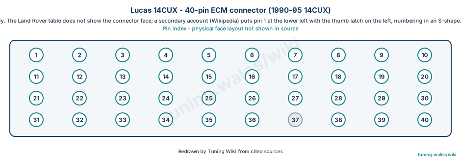
Select a pin in a photograph or the index to highlight it.
| Pin | Function / cavity | Confidence / source | Notes |
|---|---|---|---|
| Idle air valve (stepper) D Cavity: Populated |
Confirmed | 13CU/14CU/14CUX same | |
| Battery + main relay Cavity: Populated |
Confirmed | ||
| TPS reference voltage (5 V) Cavity: Populated |
Confirmed | ||
| Lambda ground Cavity: Populated |
Confirmed | ||
| Tune resistor (1990 only) Cavity: Populated |
Confirmed | 1987: rear screen input; 1988: not connected; 1989: A/C fan switch input | |
| Vehicle speed input Cavity: Populated |
Confirmed | ||
| Water temperature input Cavity: Populated |
Confirmed | ||
| Heated front screen input Cavity: Populated |
Confirmed | Not connected on 13CU | |
| Serial link (diagnostic) Cavity: Populated |
Confirmed | TestBook uses pins 9 and 18 | |
| Check Engine light (MIL) Cavity: Populated |
Confirmed | Labelled EFI light on 13CU/14CU | |
| Bank B injector ground Cavity: Populated |
Confirmed | ||
| Main relay request Cavity: Populated |
Confirmed | ||
| Bank A injector ground Cavity: Populated |
Confirmed | ||
| ECM ground Cavity: Populated |
Confirmed | ||
| Battery + Cavity: Populated |
Confirmed | ||
| Fuel pump relay request Cavity: Populated |
Confirmed | ||
| Purge control Cavity: Populated |
Confirmed | Not connected on 13CU | |
| Serial link (diagnostic) Cavity: Populated |
Confirmed | ||
| Ignition ON input Cavity: Populated |
Confirmed | ||
| TPS input Cavity: Populated |
Confirmed | ||
| A/C clutch input Cavity: Populated |
Confirmed | ||
| Air flow meter idle trim Cavity: Populated |
Confirmed | ||
| Lambda bank A Cavity: Populated |
Confirmed | ||
| Lambda bank B Cavity: Populated |
Confirmed | ||
| Sensor signal ground Cavity: Populated |
Confirmed | Labelled sensor VE in the source on 13CU/14CUX | |
| Idle air valve (stepper) C Cavity: Populated |
Confirmed | ||
| Signal ground Cavity: Populated |
Confirmed | ||
| Idle air valve (stepper) B Cavity: Populated |
Confirmed | ||
| Idle air valve (stepper) A Cavity: Populated |
Confirmed | ||
| Fault display output Cavity: Populated |
Confirmed | Not connected on 13CU/14CU | |
| Diagnostic reset Cavity: Populated |
Confirmed | Not connected on 13CU/14CU | |
| Fuel temperature input Cavity: Populated |
Confirmed | ||
| A/C clutch output Cavity: Populated |
Confirmed | Not connected on 13CU | |
| Park/neutral input Cavity: Populated |
Confirmed | ||
| Air flow meter input Cavity: Populated |
Confirmed | ||
| Fan timer request Cavity: Populated |
Confirmed | Not connected on 13CU | |
| No connection Cavity: Unused |
Confirmed | Serial link on 13CU/14CU | |
| Fault clock output Cavity: Populated |
Confirmed | Not connected on 13CU/14CU | |
| Tachometer (engine speed) input Cavity: Populated |
Confirmed | ||
| ECM ground Cavity: Populated |
Confirmed |