The Adaptronic eMod011 is an application-specific plug-in programmable engine-management ECU. Haltech's surviving Adaptronic downloads archive identifies the application as Mazda RX-7 FD Series 6. The part number identifies a family of applications, not an unconditional guarantee of vehicle compatibility. Haltech Adaptronic downloads archive.
Application and installation
Identify the vehicle, engine, connector and wiring variation before installation. Plug-in installation can still require additional sensor and actuator wiring, and tuning to suit the specific engine. The manufacturer archive provides the Adaptronic plug-in ECU startup guide and EUGENE tuning software.
Model-specific pinout
In the eMod011 section of the manufacturer download archive, find: RX7_S6_Pinout.zip. Open the matching vehicle-specific diagram; connector or pin functions cannot safely be inferred from a different eMod or a different application. The archive also lists the following basemap resource: eMod011_RX7S6_Basemap.ecu.
RX-7 Series 6 FD Twin Turbo connector assignments
From Adaptronic’s eMod011 RX7 S6 pinout archive, for the Mazda RX-7 FD Series 6 13B REW twin turbo. The connector is viewed looking into the ECU and functions refer to the Adaptronic ECU. NC means no connection per source; module positions depend on installed hardware. Both 1Q and 1R are called digital input 1 in the diagram; 4N is marked NC but also has an AWS comment. Confirm these details with the actual equipment and manufacturer before wiring. “Bar” is the source’s inverted output designation.
| Position | Adaptronic function / notes |
|---|---|
| 1A | NC |
| 1B | 12 V ignition power input |
| 1C | NC |
| 1D | CAS 3 (flex fuel input) |
| 1E | Digital input 4 (A/C switch) |
| 1F | Fuel pressure |
| 1G | Ignition output 3 (trailing / trailing 1 direct fire) |
| 1H | Ignition output 1 (leading / leading 1 direct fire) |
| 1I | Ignition output 2 (direct-fire L2) |
| 1J | Ignition output 4 (trailing select / trailing 2 direct fire) |
| 1K | Injector output 7 (pump speed) |
| 1L | Ignition output 7 (A/C relay) |
| 1M | VSS input |
| 1N | Digital input 3 (power steering) |
| 1O | External intake MAP |
| 1P | Oil pressure |
| 1Q | Digital input 1 (clutch switch) |
| 1R | Digital input 1 (neutral switch) |
| 1S | NC |
| 1T | Fuel pump control output (optional) |
| 1U | Fuel temperature |
| 1V | Oil temperature |
| 2A | Module 1; function depends on installed module |
| 2B | Tacho output |
| 2C | External 0–5 V input 1 |
| 2D | External 0–5 V input 2 |
| 2E | CAN L |
| 2F | Module 1; function depends on installed module |
| 2G | CAN H |
| 2H | Module 1; function depends on installed module |
| 2I | Module 1; function depends on installed module |
| 2J | Module 1; function depends on installed module |
| 2K | External exhaust MAP (optional) |
| 2L | O2 input 2 (spare 0–5 V) |
| 3A | Servo (0–5 V; oil-metering pump position) |
| 3B | Digital input 2 (electrical load) |
| 3C | O2 input 1 (0–5 V) |
| 3D | Ignition output 8 (thermofan) |
| 3E | Engine coolant temperature |
| 3F | TPS 2 (spare) |
| 3G | TPS 1 |
| 3H | Module 1; function depends on installed module |
| 3I | 5 V output |
| 3J | Module 3; function depends on installed module |
| 3K | Module 3; function depends on installed module |
| 3L | Manifold air temperature |
| 3M | Knock |
| 3N | Module 3; function depends on installed module |
| 3O | Injector output 8 (double-throttle control) |
| 3P | Module 3; function depends on installed module |
| 4A | Power ground |
| 4B | Power ground |
| 4C | Power ground |
| 4D | Sensor ground |
| 4E | CAS 1 (12-tooth positive) |
| 4F | Module 3; function depends on installed module |
| 4G | CAS 2 (1-tooth positive) |
| 4H | Sensor ground |
| 4I | Ignition output 6 (oil-metering pump 2) |
| 4J | Ignition output 5 (oil-metering pump 1) |
| 4K | Ignition output 6 bar (oil-metering pump 2 inverted) |
| 4L | Ignition output 5 bar (oil-metering pump 1 inverted) |
| 4M | Module 3; function depends on installed module |
| 4N | NC; source comment also mentions AWS solenoid |
| 4O | Injector output 5 (EGR; can be third injection stage) |
| 4P | Injector output 6 (AWS; can be third injection stage) |
| 4Q | Auxiliary output 2 (idle) |
| 4R | Auxiliary output 4 (twin turbo) |
| 4S | Auxiliary output 4 (charge relief valve) |
| 4T | Auxiliary output 4 bar (charge control; inverse of 4R/4S) |
| 4U | Auxiliary output 3 (boost control) |
| 4V | Auxiliary output 1 (turbo precontrol) |
| 4W | Injector output 1 (front primary) |
| 4X | Injector output 3 (front secondary) |
| 4Y | Injector output 2 (rear primary) |
| 4Z | Injector output 4 (rear secondary) |
Documentation limits
Complete channel counts and additional variants have not been independently verified for this exact model. Haltech's Adaptronic notice records the end of Adaptronic operations in 2022; use the archived documentation and confirm present support before purchasing a used ECU.
Manufacturer connector diagram and ECU photograph
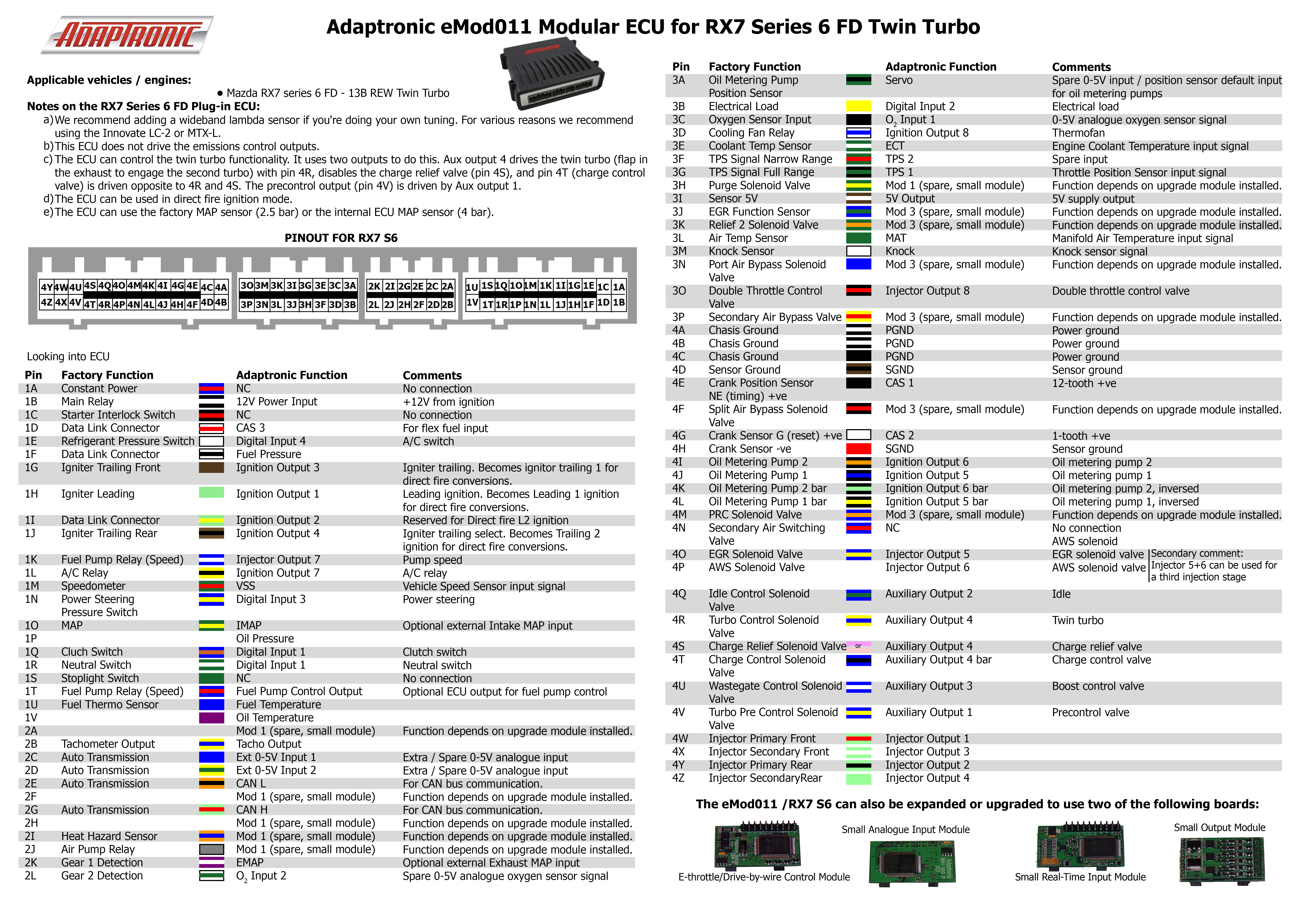
Connector pinout
A structured pinout with redrawn pin-index diagrams for all four connectors (76 positions) is on Adaptronic eMod011 connector pinout. Diagram redrawn by Tuning Wiki from the Adaptronic RX7_S6_Pinout archive (manufacturer documentation).