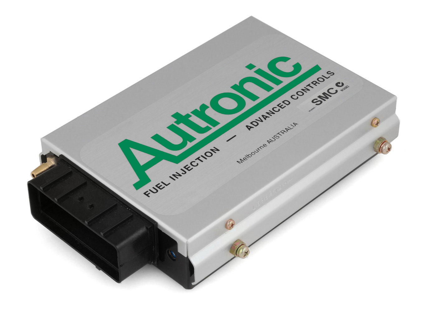
Autronic SMC is a standalone or earlier programmable engine-management system. Early SMC sequential engine management. Autronic distinguishes pre-1996 and later Rev C loom arrangements; its archive says early looms only suit pre-1996 ECUs. Model-specific information.
Identification and features
Record the ECU label, model, part number, hardware revision, firmware, configured injectors, ignition hardware and loom before comparing systems. Some outputs can be reassigned; hardware, software, current limits and engine-specific options determine what is actually available.
Processor
Autronic's product page (manufacturer documentation) gives the SMC microcontroller as a 16-bit Intel part running at 16 MHz. The exact part number is not stated in the sources checked.
Engine applications
The SMC is a universal ECU, not tied to specific vehicles. Per Autronic it suits port-injected spark-ignition engines without drive-by-wire throttle or feedback-controlled variable camshafts, including high-output supercharged or turbocharged engines, two-stroke engines, and engines with uneven firing sequences such as two- and four-cylinder V motorcycle engines and V6 car engines. Selectable cylinder counts are 1 to 8, 10, 12, 14 and 16, with full sequential injection for 2 to 8 cylinders. Hardware: eight injector drivers (selectable 4 A/1 A or 2 A/0.5 A), four open-collector ignition outputs without dwell control on the standard unit, one auxiliary output, fuel pump control, RS232 serial and a 36-way AMP connector. Positioned for high-performance motorsport; no engine codes are listed.
Wiring and pinout
Consult the Autronic SMC wiring and documentation source and identify the exact connector face, part and version. Do not apply wiring from a similarly named model. If an exact drawing is unavailable for the unit at hand, obtain it from the manufacturer or supplier before making connections.
J1 connector: manufacturer loom drawings
The 36-position J1 table, transcribed from Autronic's Type 1 pre-1996 single-relay diagram, revision 003 and universal Type 2 Rev C single-relay diagram, revision 005, with the pin 21 and 34 differences between the looms and the drawing wire colours, is on the Autronic SMC connector pinout page with a redrawn pin-index diagram (diagram redrawn by Tuning Wiki). The Type 1 loom is specified only for ECUs manufactured before 1996; the Type 2 drawing states it suits all SMC ECUs. Autronic's drawings call for calibration mode flag 11 to be set to 1 for the illustrated relay arrangement; the auxiliary and ignition output capabilities depend on the hardware and firmware fitted.
Further information
Sources
- Autronic SMC product page. Manufacturer. Accessed 19 November 2026.
- SMC loom, pre-1996 Type 1, revision 003 and Type 2 Rev C, revision 005. Manufacturer drawings. Accessed 19 November 2026.