The Autronic SMC and SMCMR use a single 36-way AMP connector, J1, water- and dust-sealed. The assignments follow two Autronic loom drawings: the Type 1 pre-1996 single-relay diagram (revision 003) and the universal Type 2 Rev C single-relay diagram (revision 005). Both are manufacturer documents. The Type 1 loom is specified only for ECUs made before 1996; the Type 2 drawing states that it suits all SMC ECUs.
Orientation and numbering
The drawings show pins 1, 13 and 25 at one end of the connector and 12, 24 and 36 at the other. The redrawn diagram uses three rows of twelve following that arrangement and is a pin index only; the viewing side and cavity spacing are not verified. The two drawings differ at pin 21 (serial I/O ground on Type 1, switch input on Type 2 Rev C) and pin 34 (not labelled on Type 1, serial I/O ground on Type 2). Wire colours in the pin notes apply to the depicted Autronic looms only.
Notable functions
J1 carries eight injector outputs, four ignition outputs and an ignition output ground, reference and cylinder pulse trigger inputs with trigger supply and ground, coolant and intake air temperature, throttle position and O2 inputs, a fuel pump output, one auxiliary output, serial receive and transmit lines, and an optional diagnostic output (drawn dashed). The drawings call for calibration mode flag 11 to be set to 1 for the illustrated relay arrangement.
Diagram redrawn by Tuning Wiki from Autronic Type 1 loom drawing revision 003 and Type 2 Rev C drawing revision 005.
Not established
Positions without a label in the drawings are not declared unused. Loom variants other than the two single-relay drawings are not covered.
Sources
- SMC wiring loom, pre-1996 Type 1, revision 003. Autronic manufacturer drawing. Accessed 19 November 2026.
- SMC wiring loom, universal Type 2 Rev C, revision 005. Autronic manufacturer drawing. Accessed 19 November 2026.
Connector pinout
Autronic SMC J1 as drawn in the Type 1 pre-1996 single-relay loom drawing (revision 003) and the universal Type 2 Rev C single-relay drawing (revision 005); manufacturer documentation. Differences at pins 21 and 34 are shown. Unlabelled drawing positions are not declared unused.
View orientation is stated beside each photograph. Unknown functions remain in the pin index.
J1 (36-way AMP connector)
View: Pin index only. The drawings show pins 1, 13 and 25 at one end and 12, 24 and 36 at the other; the index follows that row arrangement but the viewing side is not verified.
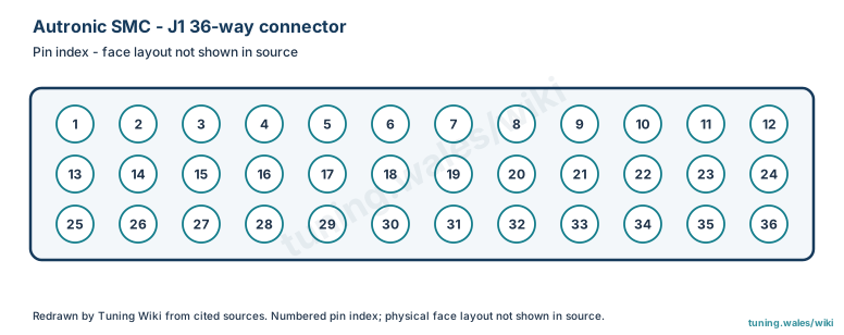
Select a pin in a photograph or the index to highlight it.
| Pin | Function / cavity | Confidence / source | Notes |
|---|---|---|---|
| Injector 7 output Cavity: Populated |
Confirmed Autronic SMC loom drawings |
Drawing wire colour: Grey/blue. | |
| Injector 6 output Cavity: Populated |
Confirmed Autronic SMC loom drawings |
Drawing wire colour: Blue/black. | |
| Injector 4 output Cavity: Populated |
Confirmed Autronic SMC loom drawings |
Drawing wire colour: Green/white. | |
| Injector 2 output Cavity: Populated |
Confirmed Autronic SMC loom drawings |
Drawing wire colour: Orange/black. | |
| Injector 1 output Cavity: Populated |
Confirmed Autronic SMC loom drawings |
Drawing wire colour: Pink/black. | |
| Coolant temperature input Cavity: Populated |
Confirmed Autronic SMC loom drawings |
Drawing wire colour: Pink. | |
| O2 input Cavity: Populated |
Confirmed Autronic SMC loom drawings |
Drawing wire colour: Blue. | |
| Reference trigger input Cavity: Populated |
Confirmed Autronic SMC loom drawings |
Drawing wire colour: Green. | |
| Serial RX Cavity: Populated |
Confirmed Autronic SMC loom drawings |
Drawing wire colour: Purple. | |
| Ignition 4 output Cavity: Populated |
Confirmed Autronic SMC loom drawings |
||
| Ignition 2 output Cavity: Populated |
Confirmed Autronic SMC loom drawings |
||
| Auxiliary output Cavity: Populated |
Confirmed Autronic SMC loom drawings |
Drawing wire colour: Grey. | |
| ECU +12 V supply Cavity: Populated |
Confirmed Autronic SMC loom drawings |
Drawing wire colour: Red. | |
| Injector 8 output Cavity: Populated |
Confirmed Autronic SMC loom drawings |
Drawing wire colour: Blue/red. | |
| Injector 5 output Cavity: Populated |
Confirmed Autronic SMC loom drawings |
Drawing wire colour: Green/yellow. | |
| Injector 3 output Cavity: Populated |
Confirmed Autronic SMC loom drawings |
Drawing wire colour: Blue/white. | |
| Sensor ground Cavity: Populated |
Confirmed Autronic SMC loom drawings |
Drawing wire colour: Black. | |
| Throttle position input Cavity: Populated |
Confirmed Autronic SMC loom drawings |
Drawing wire colour: Orange. | |
| Throttle position supply Cavity: Populated |
Confirmed Autronic SMC loom drawings |
Drawing wire colour: Red/white. | |
| Trigger supply Cavity: Populated |
Confirmed Autronic SMC loom drawings |
Drawing wire colour: Red/black. | |
| Serial I/O ground (Type 1 loom) / switch input (Type 2 Rev C loom) Cavity: Populated |
Confirmed Autronic SMC loom drawings |
Drawing wire colour: Black (Type 1) / green-orange (Type 2). | |
| Ignition 3 output Cavity: Populated |
Confirmed Autronic SMC loom drawings |
||
| Diagnostic output (optional connection) Cavity: Populated |
Confirmed Autronic SMC loom drawings |
||
| Fuel pump output Cavity: Populated |
Confirmed Autronic SMC loom drawings |
Drawing wire colour: Blue. | |
| +12 V / pump relay supply Cavity: Populated |
Confirmed Autronic SMC loom drawings |
Drawing wire colour: Red. | |
| +12 V / auxiliary output supply Cavity: Populated |
Confirmed Autronic SMC loom drawings |
Drawing wire colour: Pink/yellow. | |
| ECU ground Cavity: Populated |
Confirmed Autronic SMC loom drawings |
Drawing wire colour: Black. | |
| ECU ground Cavity: Populated |
Confirmed Autronic SMC loom drawings |
Drawing wire colour: Black. | |
| Ignition switch input Cavity: Populated |
Confirmed Autronic SMC loom drawings |
Drawing wire colour: Red. | |
| Intake air temperature input Cavity: Populated |
Confirmed Autronic SMC loom drawings |
Drawing wire colour: White. | |
| Trigger ground Cavity: Populated |
Confirmed Autronic SMC loom drawings |
Drawing wire colour: Black. | |
| Cylinder pulse trigger input Cavity: Populated |
Confirmed Autronic SMC loom drawings |
Drawing wire colour: Yellow. | |
| Serial TX Cavity: Populated |
Confirmed Autronic SMC loom drawings |
Drawing wire colour: Orange. | |
| Serial I/O ground (Type 2 Rev C loom); not labelled on Type 1 loom Cavity: Populated |
Confirmed Autronic SMC loom drawings |
Drawing wire colour: Black (Type 2). | |
| Ignition 1 output Cavity: Populated |
Confirmed Autronic SMC loom drawings |
Drawing wire colour: Pink/white. | |
| Ignition output ground Cavity: Populated |
Confirmed Autronic SMC loom drawings |