Tuning Wiki

This is a historical revision. Read the current page or return to its history.

Page organisation in this revision
Page type
Technical article
Subject
Engine ECU
Parent
AEM EMS-4
Applies to
AEM EMS-4
Tool groups
None
Manufacturers
AEM

Changes from revision 1 to revision 1

Removed text is struck through; added text is highlighted.

The AEM EMS-4 (part 30-6905) uses a single 36-pin ECU connector. The pin functions below are taken from the harness drawings in the AEM EMS-4 installation and tuning guide, revision 1.6 (manufacturer documentation), which show the same assignments for the full and mini harness.

Connector layout

The diagram redraws the two-column connector face shown in AEM's mini-harness drawing, which is captioned as viewed from the terminal end: pins 1 to 18 run upward in one column and pins 19 to 36 in the other.

Notes

Coil outputs are 0-5 V falling-edge logic signals and must not be connected to a coil primary directly.GPIO 5 to 8 are PWM capable; GPIO 1 to 4 are low-side output, 0-5 V analog input or switch input pins, with a 1.5 A rating per AEM's specification table.Injector outputs are for high-impedance injectors only (8 ohm minimum).

See the hub page AEM EMS-4.

Sources

AEM EMS-4 Install and Tuning Guide, rev 1.6, AEM Performance Electronics, pages 7 to 9. Accessed 19 November 2026.

Diagram redrawn by Tuning Wiki from the AEM harness drawing.

Rendered revisions

Open each version to inspect formatting, tables and photographs.

Revision 1: AEM EMS-4 connector pinout

The AEM EMS-4 (part 30-6905) uses a single 36-pin ECU connector. The pin functions below are taken from the harness drawings in the AEM EMS-4 installation and tuning guide, revision 1.6 (manufacturer documentation), which show the same assignments for the full and mini harness.

Connector layout

The diagram redraws the two-column connector face shown in AEM's mini-harness drawing, which is captioned as viewed from the terminal end: pins 1 to 18 run upward in one column and pins 19 to 36 in the other.

Notes

  • Coil outputs are 0-5 V falling-edge logic signals and must not be connected to a coil primary directly.
  • GPIO 5 to 8 are PWM capable; GPIO 1 to 4 are low-side output, 0-5 V analog input or switch input pins, with a 1.5 A rating per AEM's specification table.
  • Injector outputs are for high-impedance injectors only (8 ohm minimum).

See the hub page AEM EMS-4.

Sources

Diagram redrawn by Tuning Wiki from the AEM harness drawing.

Connector pinout

Applicability

AEM EMS-4 (30-6905) 36-pin main ECU connector from the AEM EMS-4 installation and tuning guide rev 1.6 (manufacturer documentation). Layout as viewed from the terminal end per the AEM harness drawing.

View orientation is stated beside each photograph. Unknown functions remain in the pin index.

Main ECU connector (36-pin)

Connector layout redrawn from AEM harness drawing
View: Viewed from the terminal end (AEM drawing)
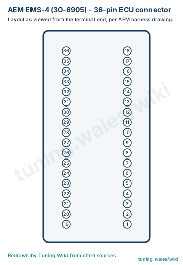
Main ECU connector (36-pin) — Connector layout redrawn from AEM harness drawing. Viewed from the terminal end (AEM drawing)

Select a pin in a photograph or the index to highlight it.

Main ECU connector (36-pin) — complete pin index
PinFunction / cavityConfidence / sourceNotes
Switched 12 V input
Cavity: Populated
Confirmed

AEM EMS-4 guide rev 1.6

Injector 1
Cavity: Populated
Confirmed

AEM EMS-4 guide rev 1.6

Injector 2
Cavity: Populated
Confirmed

AEM EMS-4 guide rev 1.6

Injector 3
Cavity: Populated
Confirmed

AEM EMS-4 guide rev 1.6

Injector 4
Cavity: Populated
Confirmed

AEM EMS-4 guide rev 1.6

Coil 1 output
Cavity: Populated
Confirmed

AEM EMS-4 guide rev 1.6

Coil 2 output
Cavity: Populated
Confirmed

AEM EMS-4 guide rev 1.6

Coil 3 output
Cavity: Populated
Confirmed

AEM EMS-4 guide rev 1.6

Coil 4 output
Cavity: Populated
Confirmed

AEM EMS-4 guide rev 1.6

GPIO 1
Cavity: Populated
Confirmed

AEM EMS-4 guide rev 1.6

GPIO 2
Cavity: Populated
Confirmed

AEM EMS-4 guide rev 1.6

GPIO 3
Cavity: Populated
Confirmed

AEM EMS-4 guide rev 1.6

GPIO 4
Cavity: Populated
Confirmed

AEM EMS-4 guide rev 1.6

GPIO 5 (PWM capable)
Cavity: Populated
Confirmed

AEM EMS-4 guide rev 1.6

GPIO 6 (PWM capable)
Cavity: Populated
Confirmed

AEM EMS-4 guide rev 1.6

GPIO 7 (PWM capable)
Cavity: Populated
Confirmed

AEM EMS-4 guide rev 1.6

GPIO 8 (PWM capable)
Cavity: Populated
Confirmed

AEM EMS-4 guide rev 1.6

Battery negative
Cavity: Populated
Confirmed

AEM EMS-4 guide rev 1.6

Battery negative
Cavity: Populated
Confirmed

AEM EMS-4 guide rev 1.6

O2 sensor input
Cavity: Populated
Confirmed

AEM EMS-4 guide rev 1.6

Cam sensor magnetic input
Cavity: Populated
Confirmed

AEM EMS-4 guide rev 1.6

Crank sensor magnetic input
Cavity: Populated
Confirmed

AEM EMS-4 guide rev 1.6

Vehicle speed sensor Hall input
Cavity: Populated
Confirmed

AEM EMS-4 guide rev 1.6

Cam sensor Hall input
Cavity: Populated
Confirmed

AEM EMS-4 guide rev 1.6

Crank sensor Hall input
Cavity: Populated
Confirmed

AEM EMS-4 guide rev 1.6

Knock sensor 1 input
Cavity: Populated
Confirmed

AEM EMS-4 guide rev 1.6

Throttle position sensor
Cavity: Populated
Confirmed

AEM EMS-4 guide rev 1.6

Manifold pressure sensor
Cavity: Populated
Confirmed

AEM EMS-4 guide rev 1.6

Coolant temperature sensor
Cavity: Populated
Confirmed

AEM EMS-4 guide rev 1.6

Inlet air temperature sensor
Cavity: Populated
Confirmed

AEM EMS-4 guide rev 1.6

USB data -
Cavity: Populated
Confirmed

AEM EMS-4 guide rev 1.6

USB data +
Cavity: Populated
Confirmed

AEM EMS-4 guide rev 1.6

CAN +
Cavity: Populated
Confirmed

AEM EMS-4 guide rev 1.6

CAN -
Cavity: Populated
Confirmed

AEM EMS-4 guide rev 1.6

Sensor ground
Cavity: Populated
Confirmed

AEM EMS-4 guide rev 1.6

VCC / sensor supply
Cavity: Populated
Confirmed

AEM EMS-4 guide rev 1.6

Revision 1: AEM EMS-4 connector pinout

The AEM EMS-4 (part 30-6905) uses a single 36-pin ECU connector. The pin functions below are taken from the harness drawings in the AEM EMS-4 installation and tuning guide, revision 1.6 (manufacturer documentation), which show the same assignments for the full and mini harness.

Connector layout

The diagram redraws the two-column connector face shown in AEM's mini-harness drawing, which is captioned as viewed from the terminal end: pins 1 to 18 run upward in one column and pins 19 to 36 in the other.

Notes

  • Coil outputs are 0-5 V falling-edge logic signals and must not be connected to a coil primary directly.
  • GPIO 5 to 8 are PWM capable; GPIO 1 to 4 are low-side output, 0-5 V analog input or switch input pins, with a 1.5 A rating per AEM's specification table.
  • Injector outputs are for high-impedance injectors only (8 ohm minimum).

See the hub page AEM EMS-4.

Sources

Diagram redrawn by Tuning Wiki from the AEM harness drawing.

Connector pinout

Applicability

AEM EMS-4 (30-6905) 36-pin main ECU connector from the AEM EMS-4 installation and tuning guide rev 1.6 (manufacturer documentation). Layout as viewed from the terminal end per the AEM harness drawing.

View orientation is stated beside each photograph. Unknown functions remain in the pin index.

Main ECU connector (36-pin)

Connector layout redrawn from AEM harness drawing
View: Viewed from the terminal end (AEM drawing)
Main ECU connector (36-pin) — Connector layout redrawn from AEM harness drawing. Viewed from the terminal end (AEM drawing)

Select a pin in a photograph or the index to highlight it.

Main ECU connector (36-pin) — complete pin index
PinFunction / cavityConfidence / sourceNotes
Switched 12 V input
Cavity: Populated
Confirmed

AEM EMS-4 guide rev 1.6

Injector 1
Cavity: Populated
Confirmed

AEM EMS-4 guide rev 1.6

Injector 2
Cavity: Populated
Confirmed

AEM EMS-4 guide rev 1.6

Injector 3
Cavity: Populated
Confirmed

AEM EMS-4 guide rev 1.6

Injector 4
Cavity: Populated
Confirmed

AEM EMS-4 guide rev 1.6

Coil 1 output
Cavity: Populated
Confirmed

AEM EMS-4 guide rev 1.6

Coil 2 output
Cavity: Populated
Confirmed

AEM EMS-4 guide rev 1.6

Coil 3 output
Cavity: Populated
Confirmed

AEM EMS-4 guide rev 1.6

Coil 4 output
Cavity: Populated
Confirmed

AEM EMS-4 guide rev 1.6

GPIO 1
Cavity: Populated
Confirmed

AEM EMS-4 guide rev 1.6

GPIO 2
Cavity: Populated
Confirmed

AEM EMS-4 guide rev 1.6

GPIO 3
Cavity: Populated
Confirmed

AEM EMS-4 guide rev 1.6

GPIO 4
Cavity: Populated
Confirmed

AEM EMS-4 guide rev 1.6

GPIO 5 (PWM capable)
Cavity: Populated
Confirmed

AEM EMS-4 guide rev 1.6

GPIO 6 (PWM capable)
Cavity: Populated
Confirmed

AEM EMS-4 guide rev 1.6

GPIO 7 (PWM capable)
Cavity: Populated
Confirmed

AEM EMS-4 guide rev 1.6

GPIO 8 (PWM capable)
Cavity: Populated
Confirmed

AEM EMS-4 guide rev 1.6

Battery negative
Cavity: Populated
Confirmed

AEM EMS-4 guide rev 1.6

Battery negative
Cavity: Populated
Confirmed

AEM EMS-4 guide rev 1.6

O2 sensor input
Cavity: Populated
Confirmed

AEM EMS-4 guide rev 1.6

Cam sensor magnetic input
Cavity: Populated
Confirmed

AEM EMS-4 guide rev 1.6

Crank sensor magnetic input
Cavity: Populated
Confirmed

AEM EMS-4 guide rev 1.6

Vehicle speed sensor Hall input
Cavity: Populated
Confirmed

AEM EMS-4 guide rev 1.6

Cam sensor Hall input
Cavity: Populated
Confirmed

AEM EMS-4 guide rev 1.6

Crank sensor Hall input
Cavity: Populated
Confirmed

AEM EMS-4 guide rev 1.6

Knock sensor 1 input
Cavity: Populated
Confirmed

AEM EMS-4 guide rev 1.6

Throttle position sensor
Cavity: Populated
Confirmed

AEM EMS-4 guide rev 1.6

Manifold pressure sensor
Cavity: Populated
Confirmed

AEM EMS-4 guide rev 1.6

Coolant temperature sensor
Cavity: Populated
Confirmed

AEM EMS-4 guide rev 1.6

Inlet air temperature sensor
Cavity: Populated
Confirmed

AEM EMS-4 guide rev 1.6

USB data -
Cavity: Populated
Confirmed

AEM EMS-4 guide rev 1.6

USB data +
Cavity: Populated
Confirmed

AEM EMS-4 guide rev 1.6

CAN +
Cavity: Populated
Confirmed

AEM EMS-4 guide rev 1.6

CAN -
Cavity: Populated
Confirmed

AEM EMS-4 guide rev 1.6

Sensor ground
Cavity: Populated
Confirmed

AEM EMS-4 guide rev 1.6

VCC / sensor supply
Cavity: Populated
Confirmed

AEM EMS-4 guide rev 1.6