The Autronic SM4 standalone engine ECU uses a single 42-way main connector. This reference gives the function of every pin as published by Autronic, with the manufacturer's current and frequency limits and the wire colour used in the standard Autronic loom. The same assignment applies to the SM4DC dual-calibration and SM4 Marine versions, which Autronic wires with the standard SM4 loom; on SM4DC units pin 39 is the calibration select input instead of a speed input.
Connector layout
The Autronic wiring drawing shows the connector from the wire side in three staggered columns of fourteen: pins 1–14, 15–28 and 29–42, with the lowest number of each column at the bottom. The interactive diagram on this page follows that arrangement; cavity spacing is schematic, so terminal positions should be checked against the actual housing before wiring.
Pin groups
- Supplies and grounds: 1 ignition-on input, 15 main +12 V supply, 30 keep-alive memory supply, 29 power ground, 22 sensor ground, 36 +5 V sensor supply (45 mA), 11 +8 V trigger supply (30 mA).
- Injectors: 17, 32, 31 and 16 form group 1–4; 4, 18, 3 and 2 form group 5–8. Injectors 6, 7 and 8 (pins 18, 3 and 2) can instead be used as switch-to-ground inputs.
- Ignition: 5, 6, 19 and 33, push-pull, 0.8 A continuous.
- Triggers: 25/40 cylinder and 26/41 sync inputs for Hall or reluctor sensors; the negative inputs are left unconnected with Hall sensors.
- Auxiliary outputs: outputs 1–4 (7, 34, 20, 35) are push-pull stepper-capable drivers; outputs 5–8 (27, 13, 42, 12) and PWM 1–2 (28, 14) are open-collector.
- Sensor inputs: 9 coolant, 23 air temperature, 21 throttle position, 37 oxygen, 8 and 38 analogue, 10, 24 and 39 high-speed inputs.
Manufacturer cautions
Pin 22 is a dedicated sensor ground and must not be joined to the engine block or vehicle ground. The ECU measures pin 15 as battery voltage for injector dead-time compensation, so pin 15 must be fed from the same supply as the injectors. Ignition 2–4 and injector outputs used for other loads are limited to ON/OFF or 10 Hz PWM operation.
Diagram redrawn by Tuning Wiki from the Autronic SM4 Wiring Basic drawing and the Autronic SM4 pin-function table.
Not established
The connector housing manufacturer and part number, and the exact physical cavity pitch, are not stated in the cited Autronic documents.
Sources
- Autronic SM4 – Input / Output Pin Functions. Autronic, manufacturer pin-function table, 12 October 2016. Accessed 19 November 2026.
- SM4 Wiring Basic. Aubert Electronics Pty Ltd, manufacturer wiring diagram SM4_0001, revision 3.4, 23 September 2014; connector shown from the wire side. Accessed 19 November 2026.
- SM4 ECU. Autronic, manufacturer product and specification page. Accessed 19 November 2026.
Connector pinout
Autronic SM4, SM4DC (dual calibration) and SM4 Marine with the standard 42-way loom. Manufacturer documentation (Autronic pin-function table dated 12 October 2016 and SM4 Wiring Basic drawing rev. 3.4, 23 September 2014). Loom colours are those of the Autronic standard harness and may differ on custom looms.
View orientation is stated beside each photograph. Unknown functions remain in the pin index.
Main connector (42-way)
View: Harness connector viewed from the wire side, as drawn in the Autronic SM4 Wiring Basic drawing; cavity spacing schematic.
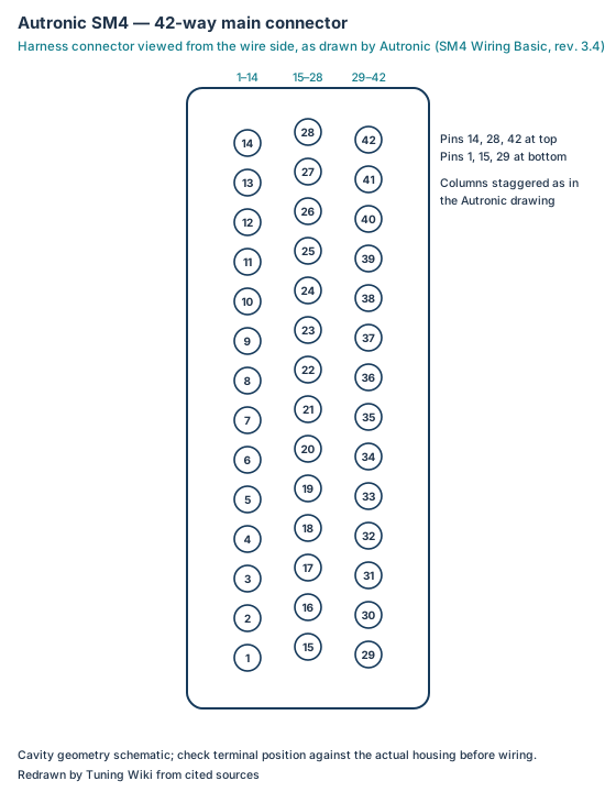
Select a pin in a photograph or the index to highlight it.
| Pin | Function / cavity | Confidence / source | Notes |
|---|---|---|---|
| Ignition switch input Cavity: Populated |
Confirmed Autronic pin table 2016; wiring rev 3.4 |
Ignition-on supply, <100 mA. Standard loom colour PUR. | |
| Injector 8 / switch input 3 Cavity: Populated |
Confirmed Autronic pin table 2016; wiring rev 3.4 |
Output in injector group 5-8 or switch-to-ground input (200 Hz max). Loom BLU/RED. | |
| Injector 7 / switch input 2 Cavity: Populated |
Confirmed Autronic pin table 2016; wiring rev 3.4 |
Output in injector group 5-8 or switch-to-ground input (200 Hz max). Loom GRY/BLU. | |
| Injector 5 Cavity: Populated |
Confirmed Autronic pin table 2016; wiring rev 3.4 |
Injector group 5-8, selectable peak/hold current. Loom GRN/YEL. | |
| Ignition 1 Cavity: Populated |
Confirmed Autronic pin table 2016; wiring rev 3.4 |
Ignition trigger, push-pull, 0.8 A continuous (1 A peak). Loom PNK/WHT. | |
| Ignition 2 Cavity: Populated |
Confirmed Autronic pin table 2016; wiring rev 3.4 |
Push-pull 0.8 A; alternate use ON/OFF or 10 Hz PWM only. Loom PNK/BLK. | |
| Output 1 Cavity: Populated |
Confirmed Autronic pin table 2016; wiring rev 3.4 |
Stepper motor or push-pull output, 0.8 A; ON/OFF, 10-500 Hz PWM or H-bridge. Loom RED/GRN. | |
| Analogue input 1 Cavity: Populated |
Confirmed Autronic pin table 2016; wiring rev 3.4 |
Spare temperature/pressure, potentiometer or high-side switch; 2-wire sensors need a pull-up. Loom GRY/BLU. | |
| Coolant temperature input Cavity: Populated |
Confirmed Autronic pin table 2016; wiring rev 3.4 |
Most NTC or PTC sensors. Loom PNK. | |
| HSI 1 Cavity: Populated |
Confirmed Autronic pin table 2016; wiring rev 3.4 |
Speed or camshaft-position input; alternate switch or digital airflow; 7 kHz max. Loom BLU. | |
| +8 V trigger supply Cavity: Populated |
Confirmed Autronic pin table 2016; wiring rev 3.4 |
Hall and other sensors, 30 mA max. Loom RED/BLK. | |
| Output 8 / tacho Cavity: Populated |
Confirmed Autronic pin table 2016; wiring rev 3.4 |
Open collector, 1 A; constant or switched supply. Loom GRY/BLK. | |
| Output 6 Cavity: Populated |
Confirmed Autronic pin table 2016; wiring rev 3.4 |
Open collector, 2.5 A. Loom BLU. | |
| PWM 2 Cavity: Populated |
Confirmed Autronic pin table 2016; wiring rev 3.4 |
Open collector 9.5-1220 Hz PWM, 3.5 A continuous (5 A peak). Loom BRN/WHT. | |
| +12 V main supply Cavity: Populated |
Confirmed Autronic pin table 2016; wiring rev 3.4 |
Measured as battery voltage for injector dead-time compensation; supply must match the injectors. Loom RED. | |
| Injector 4 Cavity: Populated |
Confirmed Autronic pin table 2016; wiring rev 3.4 |
Injector group 1-4. Loom GRN/WHT. | |
| Injector 1 Cavity: Populated |
Confirmed Autronic pin table 2016; wiring rev 3.4 |
Injector group 1-4, selectable peak/hold current. Loom PNK/BLK. | |
| Injector 6 / switch input 1 Cavity: Populated |
Confirmed Autronic pin table 2016; wiring rev 3.4 |
Output in injector group 5-8 or switch-to-ground input (700 Hz max). Loom BLU/BLK. | |
| Ignition 3 Cavity: Populated |
Confirmed Autronic pin table 2016; wiring rev 3.4 |
Push-pull 0.8 A; alternate use ON/OFF or 10 Hz PWM only. Loom YEL/BLK. | |
| Output 3 Cavity: Populated |
Confirmed Autronic pin table 2016; wiring rev 3.4 |
Push-pull 0.8 A; stepper, ON/OFF, PWM or H-bridge. Loom ORG/WHT. | |
| Throttle position input Cavity: Populated |
Confirmed Autronic pin table 2016; wiring rev 3.4 |
Linear, voltage rising with opening. Loom ORG. | |
| Signal ground Cavity: Populated |
Confirmed Autronic pin table 2016; wiring rev 3.4 |
Sensor ground; do not connect to engine block or vehicle ground. Loom BLK. | |
| Air intake temperature input Cavity: Populated |
Confirmed Autronic pin table 2016; wiring rev 3.4 |
Autronic and most NTC/PTC sensors. Loom WHT. | |
| HSI 2 Cavity: Populated |
Confirmed Autronic pin table 2016; wiring rev 3.4 |
Switch or digital flex-fuel input; 7 kHz max. Loom GRN. | |
| Cylinder trigger + Cavity: Populated |
Confirmed Autronic pin table 2016; wiring rev 3.4 |
Hall or reluctor input, generic and OEM trigger patterns. Loom WHT (screened). | |
| Sync trigger + Cavity: Populated |
Confirmed Autronic pin table 2016; wiring rev 3.4 |
Hall or reluctor sync input; alternate speed input; 7 kHz max. Loom WHT (screened). | |
| Output 5 Cavity: Populated |
Confirmed Autronic pin table 2016; wiring rev 3.4 |
Open collector, 2.5 A. Loom PNK/YEL. | |
| PWM 1 Cavity: Populated |
Confirmed Autronic pin table 2016; wiring rev 3.4 |
Open collector 9.5-1220 Hz PWM, 5 A continuous (6 A peak). Loom RED/YEL. | |
| Power ground Cavity: Populated |
Confirmed Autronic pin table 2016; wiring rev 3.4 |
Loom BLK. | |
| +12 V RAM (keep-alive) supply Cavity: Populated |
Confirmed Autronic pin table 2016; wiring rev 3.4 |
Continuous supply, <1 mA. Loom RED. | |
| Injector 3 Cavity: Populated |
Confirmed Autronic pin table 2016; wiring rev 3.4 |
Injector group 1-4. Loom BLU/WHT. | |
| Injector 2 Cavity: Populated |
Confirmed Autronic pin table 2016; wiring rev 3.4 |
Injector group 1-4. Loom ORG/BLK. | |
| Ignition 4 Cavity: Populated |
Confirmed Autronic pin table 2016; wiring rev 3.4 |
Push-pull 0.8 A; alternate use ON/OFF or 10 Hz PWM only. Loom RED/WHT. | |
| Output 2 Cavity: Populated |
Confirmed Autronic pin table 2016; wiring rev 3.4 |
Push-pull 0.8 A; stepper, ON/OFF, PWM or H-bridge. Loom BLK/WHT. | |
| Output 4 Cavity: Populated |
Confirmed Autronic pin table 2016; wiring rev 3.4 |
Push-pull 0.8 A; stepper, ON/OFF, PWM or H-bridge. Loom BRN/BLK. | |
| +5 V sensor supply Cavity: Populated |
Confirmed Autronic pin table 2016; wiring rev 3.4 |
TPS and other sensors, 45 mA max. Loom RED/WHT. | |
| Oxygen / AFR input Cavity: Populated |
Confirmed Autronic pin table 2016; wiring rev 3.4 |
Loom BLU. | |
| Analogue input 2 Cavity: Populated |
Confirmed Autronic pin table 2016; wiring rev 3.4 |
External MAP/BARO; labelled 'Analog 2-3' on the wiring diagram. Loom GRN/BLK. | |
| HSI 3 / dual-calibration select Cavity: Populated |
Confirmed Autronic pin table 2016; wiring rev 3.4 |
Speed input or switch, 2.2 kHz max; on SM4DC dual-calibration units this is the calibration select input. Loom GRY. | |
| Cylinder trigger - Cavity: Populated |
Confirmed Autronic pin table 2016; wiring rev 3.4 |
Reluctor negative; leave unconnected with Hall sensors. Loom BLK (screened). | |
| Sync trigger - Cavity: Populated |
Confirmed Autronic pin table 2016; wiring rev 3.4 |
Reluctor negative; leave unconnected with Hall sensors. Loom BLK (screened). | |
| Output 7 Cavity: Populated |
Confirmed Autronic pin table 2016; wiring rev 3.4 |
Open collector, 3.5 A. Loom GRN/ORG. |