Removed text is struck through; added text is highlighted.
What nitrous oxide does
Nitrous oxide (N2O) is stored as a pressurised liquid and introduced into an engine's intake when the system is activated. As it vaporises it cools the charge; in the combustion chamber it releases oxygen that allows more fuel to be burned. A petrol engine needs the corresponding additional fuel and suitable calibration. The increase in cylinder load and heat must be within the engine and drivetrain's limits. NOS is the name of a Nitrous Oxide Systems brand; people also use “NOS” informally for nitrous systems in general.
This guide is about performance nitrous oxide injection. It is distinct from NOx exhaust emissions, a term commonly used for nitrogen oxides such as nitric oxide and nitrogen dioxide.
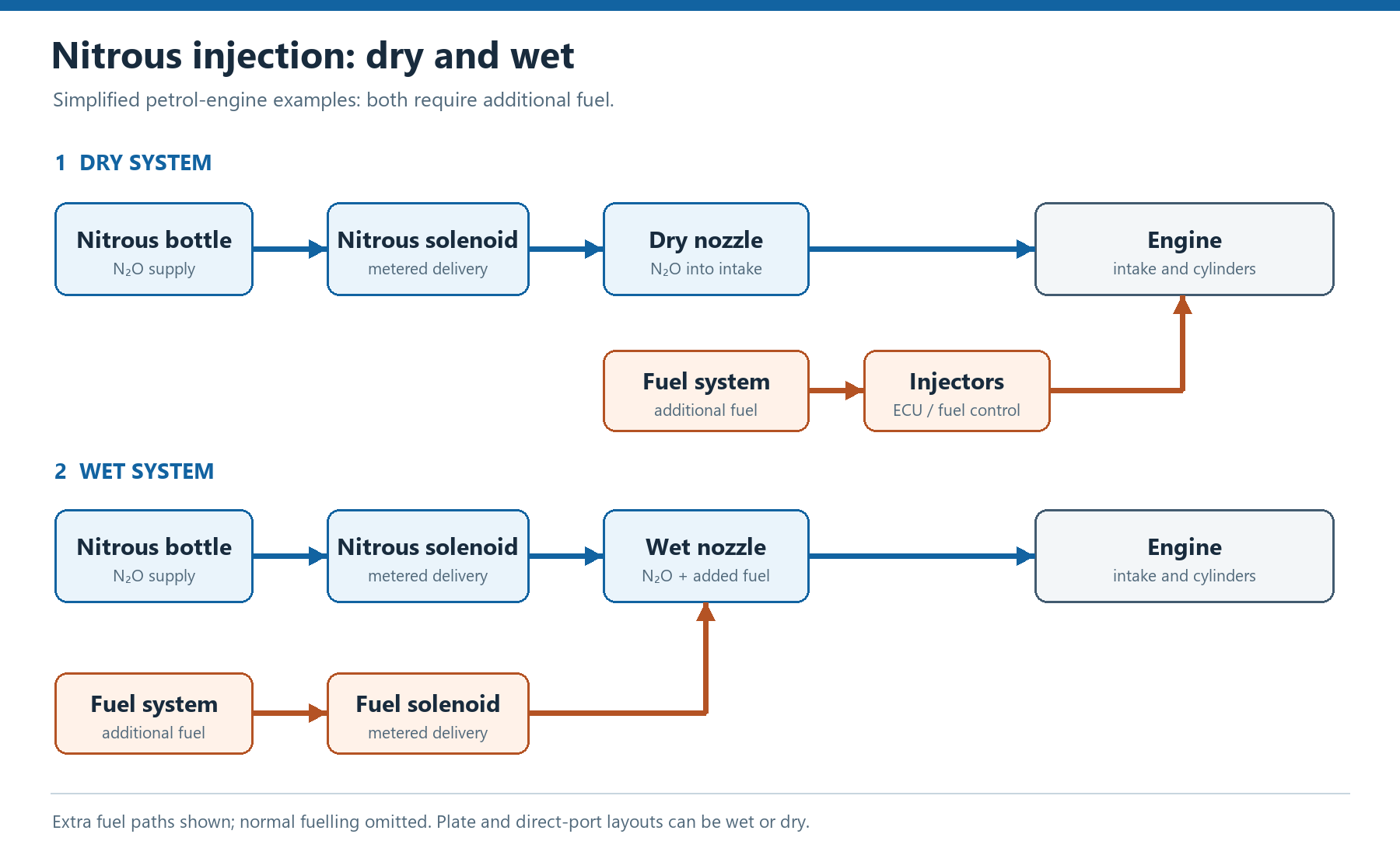
Dry and wet systems add the extra fuel in different ways. Normal engine fuelling is omitted for clarity; plate and direct-port systems can be wet or dry. Original diagram for Tuning Wiki; credit: OpenAI Codex; licence: commissioned for use on Tuning Wiki. Technical basis: Holley NOS system types and the NOS dry plate manual.
Nitrous system types, makes and trade-offs
Dry and wet describe where the extra fuel is supplied; single nozzle, plate and direct port describe where the system injects. A kit may therefore fit more than one row. Examples are specific products, not recommendations or promises that a kit fits a particular vehicle.
System or layoutExample makes or productsBenefitsDrawbacks
Dry (fuel strategy)Nitrous Express dry direct-port; NOS dry plate.Only nitrous is introduced at the nitrous outlet; no additional fuel line is needed at that outlet.The engine's fuelling system must supply the extra fuel reliably. Injector, pump, ECU and distribution capability must be verified; a dry system is not “fuel-free”.
Wet (fuel strategy)NOS Sniper Single Fogger wet kit.Supplies supplemental fuel with nitrous through the system's fuel circuit and outlet, as well as the engine's normal fuelling.Extra fuel hardware and correct fuel pressure are needed; intake layout and placement affect distribution and can permit fuel pooling. The base fuel system and tune still matter.
Single nozzle (injection location)NOS Sniper Single Fogger wet kit; kits from Nitrous Express.Compact layout with fewer injection outlets, useful where the intake permits good distribution.One upstream point relies on the manifold to distribute the charge. Fitment and distribution vary by intake and engine.
Plate (injection location)NOS wet LS plate kit; NOS dry Sniper Race plate.Places injection in a plate designed for a compatible carburettor or throttle-body/manifold flange; packaging can be tidy.Flange, clearance and distribution must suit the exact intake. A plate can be wet or dry; the word does not say where extra fuel comes from.
Direct port (injection location)NOS direct-port systems; Nitrous Express dry direct-port.An outlet at each runner offers more control over delivery to individual cylinders when correctly designed and set up.More outlets, plumbing, installation and checking. Placement, cylinder-to-cylinder distribution and fuel supply remain important; direct port can be wet or dry.
Staged or progressive control (activation strategy)NOS controllers and accessories; Nitrous Express progressive controllers.Can manage when and how delivery is introduced, helping tailor the torque rise and traction to the application.More wiring, calibration and failure points; control does not compensate for inadequate fuel, an unsuitable tune or an engine beyond its limits.
What the parts do
A bottle and valve store the nitrous; rated lines carry it to an electrically operated solenoid and metering jets or other kit-specific metering. A nozzle, plate or individual runner outlets introduce it to the intake. A wet system also has a supplemental fuel supply, fuel solenoid and metering. Exact components differ between kits; follow the correct instructions for the actual hardware and vehicle.
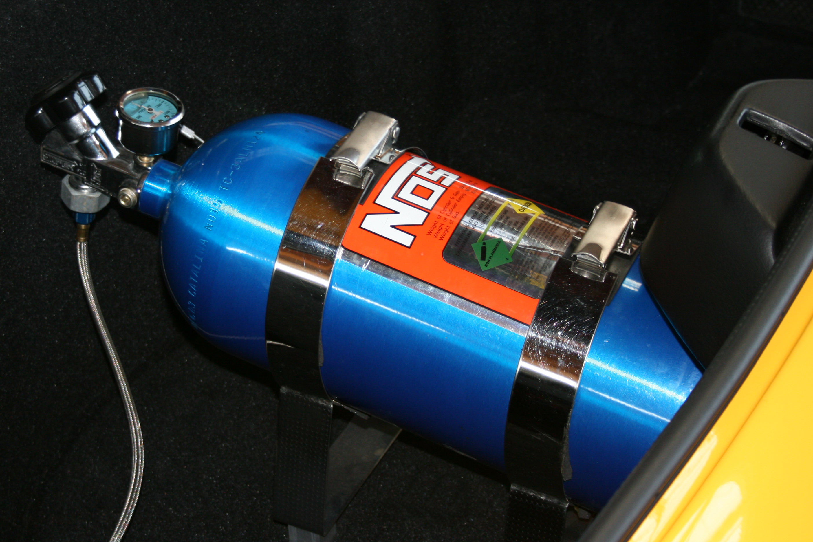
An NOS-branded nitrous bottle on a show vehicle. Photo: Stefan-Xp, Wikimedia Commons, CC BY-SA 3.0; unchanged from the Commons file. Follow the kit and bottle manufacturer's mounting and venting instructions for any installation.
Example of a nitrous-equipped engine bay in a 1963½ Ford Falcon Sprint. Photo: Hackaday, via Wikimedia Commons, CC BY-SA 2.0; unchanged from the Commons file. The picture does not establish the specification or safe setup of another car.
Fuel, control and engine matching
For a dry petrol system, the engine's injectors and control strategy must deliver the additional fuel when nitrous is active. For a wet petrol system, the extra circuit adds fuel at the nitrous outlet; it does not replace the engine's normal fuel supply. In both cases, confirm fuel pressure and capacity under load, mixture, ignition strategy and the health of the engine. Jet figures and claimed power gains are specific to the manufacturer's setup, not a safe universal setting.
Arming, throttle and engine-speed conditions can be used to control activation. A correctly selected fuel-pressure safety switch and RPM window switch, or equivalent ECU strategies where supported, can add protection. These do not prove that every cylinder receives the correct mixture. A progressive controller can change delivery over time; staged systems can bring separate stages in under specified conditions.
This comparison primarily describes petrol performance systems. Diesel systems and engines with unusual injection arrangements need a system and calibration specifically designed for that application. A nitrous system can be used alongside a turbo or supercharger only when the combined air, fuel, pressure, heat and mechanical demands are engineered together.
Dry-system fuel strategies and pressure monitoring
Dry kits do not all request extra fuel in the same way. One approach uses a compatible engine controller to command additional injector fuel when nitrous is active. Holley also describes a kit-specific method that raises the pressure applied to the fuel-pressure regulator so the existing injectors deliver more fuel. This relies on the pump, regulator, injectors and calibration having sufficient capacity for the actual combination; it is not a universal modification for another fuel system. See Holley’s explanation of dry and wet systems.
A pressure switch measures pressure at its installed location and operates at its configured threshold; it does not measure the fuel delivered by each injector or establish equal cylinder distribution. Holley describes its NOS fuel-pressure switch as a way to deactivate the system below a set pressure, with different switch ranges and a current limit for the illustrated wiring. Choose and test the protection against the specific kit instructions. Check fuel delivery, mixture and nitrous activation under representative conditions as well; a pressure reading by itself is not a complete fuelling check.
Activation, ramps and timing
An RPM window sets conditions for allowing a stage to operate; it does not itself progressively meter the nitrous. A progressive controller may instead vary a solenoid command over time, RPM or throttle position, depending on the controller. For example, the NOS Mini 2-Stage controller guide describes separate programmable channels and configurable fuel and nitrous ramps. Solenoid compatibility, output ratings and pulse frequency must match the specific hardware.
Some ECUs also use minimum and maximum manifold pressure, throttle, coolant temperature and limiter state as conditions for a stage. Haltech's nitrous-stage documentation describes these options and separate fuel and ignition corrections. It also describes on- and off-delays because the change in flow at the engine can lag the electrical solenoid command. Those settings are controller- and installation-specific; do not transfer timing values from another vehicle or assume that an electrical command proves flow has reached the cylinders.
Identify which pressure a sensor measures: intake manifold pressure, nitrous bottle pressure and fuel pressure are different signals with different purposes. Haltech describes nitrous-pressure monitoring for logging and conditional stage deactivation; a bottle-pressure input does not establish fuel delivery. Verify the configured enable and shutdown conditions, signal readings, fuel and ignition responses, and reactivation behaviour using the equipment manufacturer's test procedure before loaded operation.
Installation, distribution and output wiringChoose nozzle position and orientation for the exact kit and intake. A shared nozzle relies on the manifold for cylinder distribution; an outlet per runner allows individual placement but still requires correct jets, plumbing and verification. NOS cautions about even cylinder distribution in its single-nozzle instructions and addresses nozzle orientation and component clearance in a separate direct-port kit manual. These instructions describe different products and their positions are not universal templates.Check solenoid current, driver rating, fusing, wiring and the output's active state against the actual ECU and kit. Haltech's nitrous wiring guidance distinguishes a suitably rated high-current output from an output used to trigger a relay. Progressive pulse-width control requires a controller, output and solenoid combination specified for that switching; do not assume a conventional relay can reproduce a rapidly pulsed solenoid command. Follow the manufacturer's wiring and test procedures for the specific hardware.
Benefits, limitations and safe handling
On-demand power: an appropriately matched kit can increase output when activated, with relatively little intake hardware on some layouts.
Finite supply: output is available only while the system is operating and the bottle contains enough nitrous. Bottle temperature and pressure influence delivery; refills and inspection are ongoing costs.
Additional engine demand: excessive cylinder pressure, lean operation, knock or uneven distribution can damage an engine. Check the complete combination and monitor it under the intended load.
Pressurised oxidiser: nitrous oxide can intensify combustion and displace breathable air. Secure an approved cylinder as instructed, use compatible rated components, ventilate appropriately and follow the manufacturer's filling, heating, storage and venting instructions. Do not heat a bottle with an open flame.
Sources
NOS system types and layouts. Holley NOS. Dry, wet and direct-port concepts. Accessed 2026-11-14.
NOS dry nitrous plate owner's manual. Holley NOS. An example of a dry plate and its application-specific requirements. Accessed 2026-11-14.
NOS dry EFI Pro Fogger owner's manual. Holley NOS. Kit operation and handling precautions. Accessed 2026-11-14.
NOS Sniper Single Fogger wet system and NOS direct-port systems. Holley NOS. Example products. Accessed 2026-11-14.
Eight-cylinder dry direct-port system. Nitrous Express. Example of a dry direct-port layout. Accessed 2026-11-14.
Nitrous oxide: NIOSH Pocket Guide. US National Institute for Occupational Safety and Health. Gas and exposure hazards. Accessed 2026-11-14.
Rendered revisions
Open each version to inspect formatting, tables and photographs.
Revision 3: Nitrous oxide injection systems
What nitrous oxide does
Nitrous oxide (N2O) is stored as a pressurised liquid and introduced into an engine's intake when the system is activated. As it vaporises it cools the charge; in the combustion chamber it releases oxygen that allows more fuel to be burned. A petrol engine needs the corresponding additional fuel and suitable calibration. The increase in cylinder load and heat must be within the engine and drivetrain's limits. NOS is the name of a Nitrous Oxide Systems brand; people also use “NOS” informally for nitrous systems in general.
This guide is about performance nitrous oxide injection. It is distinct from NOx exhaust emissions, a term commonly used for nitrogen oxides such as nitric oxide and nitrogen dioxide.
Dry and wet systems add the extra fuel in different ways. Normal engine fuelling is omitted for clarity; plate and direct-port systems can be wet or dry. Original diagram for Tuning Wiki; credit: OpenAI Codex; licence: commissioned for use on Tuning Wiki. Technical basis: Holley NOS system types and the NOS dry plate manual.
Nitrous system types, makes and trade-offs
Dry and wet describe where the extra fuel is supplied; single nozzle, plate and direct port describe where the system injects. A kit may therefore fit more than one row. Examples are specific products, not recommendations or promises that a kit fits a particular vehicle.
Only nitrous is introduced at the nitrous outlet; no additional fuel line is needed at that outlet.
The engine's fuelling system must supply the extra fuel reliably. Injector, pump, ECU and distribution capability must be verified; a dry system is not “fuel-free”.
Supplies supplemental fuel with nitrous through the system's fuel circuit and outlet, as well as the engine's normal fuelling.
Extra fuel hardware and correct fuel pressure are needed; intake layout and placement affect distribution and can permit fuel pooling. The base fuel system and tune still matter.
Single nozzle (injection location)
NOS Sniper Single Fogger wet kit; kits from Nitrous Express.
Compact layout with fewer injection outlets, useful where the intake permits good distribution.
One upstream point relies on the manifold to distribute the charge. Fitment and distribution vary by intake and engine.
An outlet at each runner offers more control over delivery to individual cylinders when correctly designed and set up.
More outlets, plumbing, installation and checking. Placement, cylinder-to-cylinder distribution and fuel supply remain important; direct port can be wet or dry.
Staged or progressive control (activation strategy)
Can manage when and how delivery is introduced, helping tailor the torque rise and traction to the application.
More wiring, calibration and failure points; control does not compensate for inadequate fuel, an unsuitable tune or an engine beyond its limits.
What the parts do
A bottle and valve store the nitrous; rated lines carry it to an electrically operated solenoid and metering jets or other kit-specific metering. A nozzle, plate or individual runner outlets introduce it to the intake. A wet system also has a supplemental fuel supply, fuel solenoid and metering. Exact components differ between kits; follow the correct instructions for the actual hardware and vehicle.
An NOS-branded nitrous bottle on a show vehicle. Photo: Stefan-Xp, Wikimedia Commons, CC BY-SA 3.0; unchanged from the Commons file. Follow the kit and bottle manufacturer's mounting and venting instructions for any installation.Example of a nitrous-equipped engine bay in a 1963½ Ford Falcon Sprint. Photo: Hackaday, via Wikimedia Commons, CC BY-SA 2.0; unchanged from the Commons file. The picture does not establish the specification or safe setup of another car.
Fuel, control and engine matching
For a dry petrol system, the engine's injectors and control strategy must deliver the additional fuel when nitrous is active. For a wet petrol system, the extra circuit adds fuel at the nitrous outlet; it does not replace the engine's normal fuel supply. In both cases, confirm fuel pressure and capacity under load, mixture, ignition strategy and the health of the engine. Jet figures and claimed power gains are specific to the manufacturer's setup, not a safe universal setting.
Arming, throttle and engine-speed conditions can be used to control activation. A correctly selected fuel-pressure safety switch and RPM window switch, or equivalent ECU strategies where supported, can add protection. These do not prove that every cylinder receives the correct mixture. A progressive controller can change delivery over time; staged systems can bring separate stages in under specified conditions.
This comparison primarily describes petrol performance systems. Diesel systems and engines with unusual injection arrangements need a system and calibration specifically designed for that application. A nitrous system can be used alongside a turbo or supercharger only when the combined air, fuel, pressure, heat and mechanical demands are engineered together.
Dry-system fuel strategies and pressure monitoring
Dry kits do not all request extra fuel in the same way. One approach uses a compatible engine controller to command additional injector fuel when nitrous is active. Holley also describes a kit-specific method that raises the pressure applied to the fuel-pressure regulator so the existing injectors deliver more fuel. This relies on the pump, regulator, injectors and calibration having sufficient capacity for the actual combination; it is not a universal modification for another fuel system. See Holley’s explanation of dry and wet systems.
A pressure switch measures pressure at its installed location and operates at its configured threshold; it does not measure the fuel delivered by each injector or establish equal cylinder distribution. Holley describes its NOS fuel-pressure switch as a way to deactivate the system below a set pressure, with different switch ranges and a current limit for the illustrated wiring. Choose and test the protection against the specific kit instructions. Check fuel delivery, mixture and nitrous activation under representative conditions as well; a pressure reading by itself is not a complete fuelling check.
Activation, ramps and timing
An RPM window sets conditions for allowing a stage to operate; it does not itself progressively meter the nitrous. A progressive controller may instead vary a solenoid command over time, RPM or throttle position, depending on the controller. For example, the NOS Mini 2-Stage controller guide describes separate programmable channels and configurable fuel and nitrous ramps. Solenoid compatibility, output ratings and pulse frequency must match the specific hardware.
Some ECUs also use minimum and maximum manifold pressure, throttle, coolant temperature and limiter state as conditions for a stage. Haltech's nitrous-stage documentation describes these options and separate fuel and ignition corrections. It also describes on- and off-delays because the change in flow at the engine can lag the electrical solenoid command. Those settings are controller- and installation-specific; do not transfer timing values from another vehicle or assume that an electrical command proves flow has reached the cylinders.
Identify which pressure a sensor measures: intake manifold pressure, nitrous bottle pressure and fuel pressure are different signals with different purposes. Haltech describes nitrous-pressure monitoring for logging and conditional stage deactivation; a bottle-pressure input does not establish fuel delivery. Verify the configured enable and shutdown conditions, signal readings, fuel and ignition responses, and reactivation behaviour using the equipment manufacturer's test procedure before loaded operation.
Benefits, limitations and safe handling
On-demand power: an appropriately matched kit can increase output when activated, with relatively little intake hardware on some layouts.
Finite supply: output is available only while the system is operating and the bottle contains enough nitrous. Bottle temperature and pressure influence delivery; refills and inspection are ongoing costs.
Additional engine demand: excessive cylinder pressure, lean operation, knock or uneven distribution can damage an engine. Check the complete combination and monitor it under the intended load.
Pressurised oxidiser: nitrous oxide can intensify combustion and displace breathable air. Secure an approved cylinder as instructed, use compatible rated components, ventilate appropriately and follow the manufacturer's filling, heating, storage and venting instructions. Do not heat a bottle with an open flame.
Nitrous oxide: NIOSH Pocket Guide. US National Institute for Occupational Safety and Health. Gas and exposure hazards. Accessed 2026-11-14.
Revision 4: Nitrous oxide injection systems
What nitrous oxide does
Nitrous oxide (N2O) is stored as a pressurised liquid and introduced into an engine's intake when the system is activated. As it vaporises it cools the charge; in the combustion chamber it releases oxygen that allows more fuel to be burned. A petrol engine needs the corresponding additional fuel and suitable calibration. The increase in cylinder load and heat must be within the engine and drivetrain's limits. NOS is the name of a Nitrous Oxide Systems brand; people also use “NOS” informally for nitrous systems in general.
This guide is about performance nitrous oxide injection. It is distinct from NOx exhaust emissions, a term commonly used for nitrogen oxides such as nitric oxide and nitrogen dioxide.
Dry and wet systems add the extra fuel in different ways. Normal engine fuelling is omitted for clarity; plate and direct-port systems can be wet or dry. Original diagram for Tuning Wiki; credit: OpenAI Codex; licence: commissioned for use on Tuning Wiki. Technical basis: Holley NOS system types and the NOS dry plate manual.
Nitrous system types, makes and trade-offs
Dry and wet describe where the extra fuel is supplied; single nozzle, plate and direct port describe where the system injects. A kit may therefore fit more than one row. Examples are specific products, not recommendations or promises that a kit fits a particular vehicle.
Only nitrous is introduced at the nitrous outlet; no additional fuel line is needed at that outlet.
The engine's fuelling system must supply the extra fuel reliably. Injector, pump, ECU and distribution capability must be verified; a dry system is not “fuel-free”.
Supplies supplemental fuel with nitrous through the system's fuel circuit and outlet, as well as the engine's normal fuelling.
Extra fuel hardware and correct fuel pressure are needed; intake layout and placement affect distribution and can permit fuel pooling. The base fuel system and tune still matter.
Single nozzle (injection location)
NOS Sniper Single Fogger wet kit; kits from Nitrous Express.
Compact layout with fewer injection outlets, useful where the intake permits good distribution.
One upstream point relies on the manifold to distribute the charge. Fitment and distribution vary by intake and engine.
An outlet at each runner offers more control over delivery to individual cylinders when correctly designed and set up.
More outlets, plumbing, installation and checking. Placement, cylinder-to-cylinder distribution and fuel supply remain important; direct port can be wet or dry.
Staged or progressive control (activation strategy)
Can manage when and how delivery is introduced, helping tailor the torque rise and traction to the application.
More wiring, calibration and failure points; control does not compensate for inadequate fuel, an unsuitable tune or an engine beyond its limits.
What the parts do
A bottle and valve store the nitrous; rated lines carry it to an electrically operated solenoid and metering jets or other kit-specific metering. A nozzle, plate or individual runner outlets introduce it to the intake. A wet system also has a supplemental fuel supply, fuel solenoid and metering. Exact components differ between kits; follow the correct instructions for the actual hardware and vehicle.
An NOS-branded nitrous bottle on a show vehicle. Photo: Stefan-Xp, Wikimedia Commons, CC BY-SA 3.0; unchanged from the Commons file. Follow the kit and bottle manufacturer's mounting and venting instructions for any installation.Example of a nitrous-equipped engine bay in a 1963½ Ford Falcon Sprint. Photo: Hackaday, via Wikimedia Commons, CC BY-SA 2.0; unchanged from the Commons file. The picture does not establish the specification or safe setup of another car.
Fuel, control and engine matching
For a dry petrol system, the engine's injectors and control strategy must deliver the additional fuel when nitrous is active. For a wet petrol system, the extra circuit adds fuel at the nitrous outlet; it does not replace the engine's normal fuel supply. In both cases, confirm fuel pressure and capacity under load, mixture, ignition strategy and the health of the engine. Jet figures and claimed power gains are specific to the manufacturer's setup, not a safe universal setting.
Arming, throttle and engine-speed conditions can be used to control activation. A correctly selected fuel-pressure safety switch and RPM window switch, or equivalent ECU strategies where supported, can add protection. These do not prove that every cylinder receives the correct mixture. A progressive controller can change delivery over time; staged systems can bring separate stages in under specified conditions.
This comparison primarily describes petrol performance systems. Diesel systems and engines with unusual injection arrangements need a system and calibration specifically designed for that application. A nitrous system can be used alongside a turbo or supercharger only when the combined air, fuel, pressure, heat and mechanical demands are engineered together.
Dry-system fuel strategies and pressure monitoring
Dry kits do not all request extra fuel in the same way. One approach uses a compatible engine controller to command additional injector fuel when nitrous is active. Holley also describes a kit-specific method that raises the pressure applied to the fuel-pressure regulator so the existing injectors deliver more fuel. This relies on the pump, regulator, injectors and calibration having sufficient capacity for the actual combination; it is not a universal modification for another fuel system. See Holley’s explanation of dry and wet systems.
A pressure switch measures pressure at its installed location and operates at its configured threshold; it does not measure the fuel delivered by each injector or establish equal cylinder distribution. Holley describes its NOS fuel-pressure switch as a way to deactivate the system below a set pressure, with different switch ranges and a current limit for the illustrated wiring. Choose and test the protection against the specific kit instructions. Check fuel delivery, mixture and nitrous activation under representative conditions as well; a pressure reading by itself is not a complete fuelling check.
Activation, ramps and timing
An RPM window sets conditions for allowing a stage to operate; it does not itself progressively meter the nitrous. A progressive controller may instead vary a solenoid command over time, RPM or throttle position, depending on the controller. For example, the NOS Mini 2-Stage controller guide describes separate programmable channels and configurable fuel and nitrous ramps. Solenoid compatibility, output ratings and pulse frequency must match the specific hardware.
Some ECUs also use minimum and maximum manifold pressure, throttle, coolant temperature and limiter state as conditions for a stage. Haltech's nitrous-stage documentation describes these options and separate fuel and ignition corrections. It also describes on- and off-delays because the change in flow at the engine can lag the electrical solenoid command. Those settings are controller- and installation-specific; do not transfer timing values from another vehicle or assume that an electrical command proves flow has reached the cylinders.
Identify which pressure a sensor measures: intake manifold pressure, nitrous bottle pressure and fuel pressure are different signals with different purposes. Haltech describes nitrous-pressure monitoring for logging and conditional stage deactivation; a bottle-pressure input does not establish fuel delivery. Verify the configured enable and shutdown conditions, signal readings, fuel and ignition responses, and reactivation behaviour using the equipment manufacturer's test procedure before loaded operation.
Installation, distribution and output wiring
Choose nozzle position and orientation for the exact kit and intake. A shared nozzle relies on the manifold for cylinder distribution; an outlet per runner allows individual placement but still requires correct jets, plumbing and verification. NOS cautions about even cylinder distribution in its single-nozzle instructions and addresses nozzle orientation and component clearance in a separate direct-port kit manual. These instructions describe different products and their positions are not universal templates.
Check solenoid current, driver rating, fusing, wiring and the output's active state against the actual ECU and kit. Haltech's nitrous wiring guidance distinguishes a suitably rated high-current output from an output used to trigger a relay. Progressive pulse-width control requires a controller, output and solenoid combination specified for that switching; do not assume a conventional relay can reproduce a rapidly pulsed solenoid command. Follow the manufacturer's wiring and test procedures for the specific hardware.
Benefits, limitations and safe handling
On-demand power: an appropriately matched kit can increase output when activated, with relatively little intake hardware on some layouts.
Finite supply: output is available only while the system is operating and the bottle contains enough nitrous. Bottle temperature and pressure influence delivery; refills and inspection are ongoing costs.
Additional engine demand: excessive cylinder pressure, lean operation, knock or uneven distribution can damage an engine. Check the complete combination and monitor it under the intended load.
Pressurised oxidiser: nitrous oxide can intensify combustion and displace breathable air. Secure an approved cylinder as instructed, use compatible rated components, ventilate appropriately and follow the manufacturer's filling, heating, storage and venting instructions. Do not heat a bottle with an open flame.