ThunderMax 309-464 is a vehicle-specific standalone replacement engine-management kit for fuel-injected Harley-Davidson motorcycles. It replaces the original ECM and connects to the specified vehicle harness; it is not simply a piggyback fuel controller. ThunderMax model documentation.
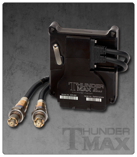
Application and identification
2008–2012 Harley-Davidson XR1200 models. Manufacturer source.
ThunderMax’s 2014 installation guide says this kit’s ECU is marked 309-460 and that the instructions and communication pigtail differ. ThunderMax also lists 309-485 for some XR1200 applications; verify the exact kit before ordering.
Check the part number, model year, throttle arrangement, vehicle equipment and the manufacturer’s current installation guide. Kit contents and engine compatibility must not be inferred from the common ThunderMax brand or another part number.
Control and installation
ThunderMax describes its replacement systems as using wideband oxygen-sensor feedback and AutoTune. Sensors, adapters, software, basemap and calibration depend on the kit and vehicle. Manufacturer system overview; installation and support documents.
Connector information
This application uses the relevant factory-style vehicle connection and the kit’s associated sensor harness. A complete pin-by-pin schedule for this exact part number has not been verified here; consult the matching installation instructions and identify the connector and harness before wiring. Do not transfer a pinout from another Harley-Davidson model or ThunderMax kit.
36-way ECM connector: 309-424 communication pigtail
The ThunderMax 309-464 installation guide calls for the 309-424 USB pigtail on the 36-position ECM harness connector. The 309-424 manufacturer instructions identify the following positions from the wire side. This is a partial communication-harness reference, not a complete ECU pinout; the guide does not identify which of the green or white leads is USB D+ or D−. Verify the actual ECM, pigtail and guide revision.
| 36-way position | 309-424 instruction |
|---|---|
| 10 | Black pigtail wire; the guide describes the original black or black/green harness wire here as a redundant ground. |
| 16 | White pigtail wire; guide identifies this position as originally sealed in its illustrated installation. |
| 32 | Green pigtail wire; guide identifies this position as originally sealed in its illustrated installation. |